Building member

a building member and static technology, applied in the direction of building scaffolds, couplings, rod connections, etc., can solve the problems of unneeded pesticide treatment, fluctuation of lumber costs, and significant challenges for builders in offering high-quality construction, and achieve the effects of convenient transportation, convenient plumbed, and reusabl

Inactive Publication Date: 2009-10-27
ELEKSEN
View PDF24 Cites 4 Cited by
  • Summary
  • Abstract
  • Description
  • Claims
  • Application Information

AI Technical Summary

Benefits of technology

[0006]In light of the problems associated with known building members formed of metal, it is a principal object of the invention to provide a metallic building member having portions that are easily transported and connected together at a construction site. The building member, being linear, is easily plumbed and, if required, is reusable.
[0008]It is an object of the invention to provide improved features and arrangements thereof in a building member for the purposes described that is lightweight in construction, inexpensive to manufacture, and dependable in use.

Problems solved by technology

Builders are confronted with significant challenges in offering high-quality construction at competitive prices.
Fluctuations in lumber costs often work against builders in making profits for their efforts.
Because it is termite-proof, pesticide treatments are also unnecessary.
Metallic building members can be difficult to use.
They are typically large and heavy, making them difficult to transport.
Furthermore, because of the significantly greater density of metal relative to wood, nails cannot be employed in connecting members together and costly techniques such as welding and riveting must be employed.

Method used


Image

  • Building member
  • Building member
  • Building member

Examples


Embodiment Construction

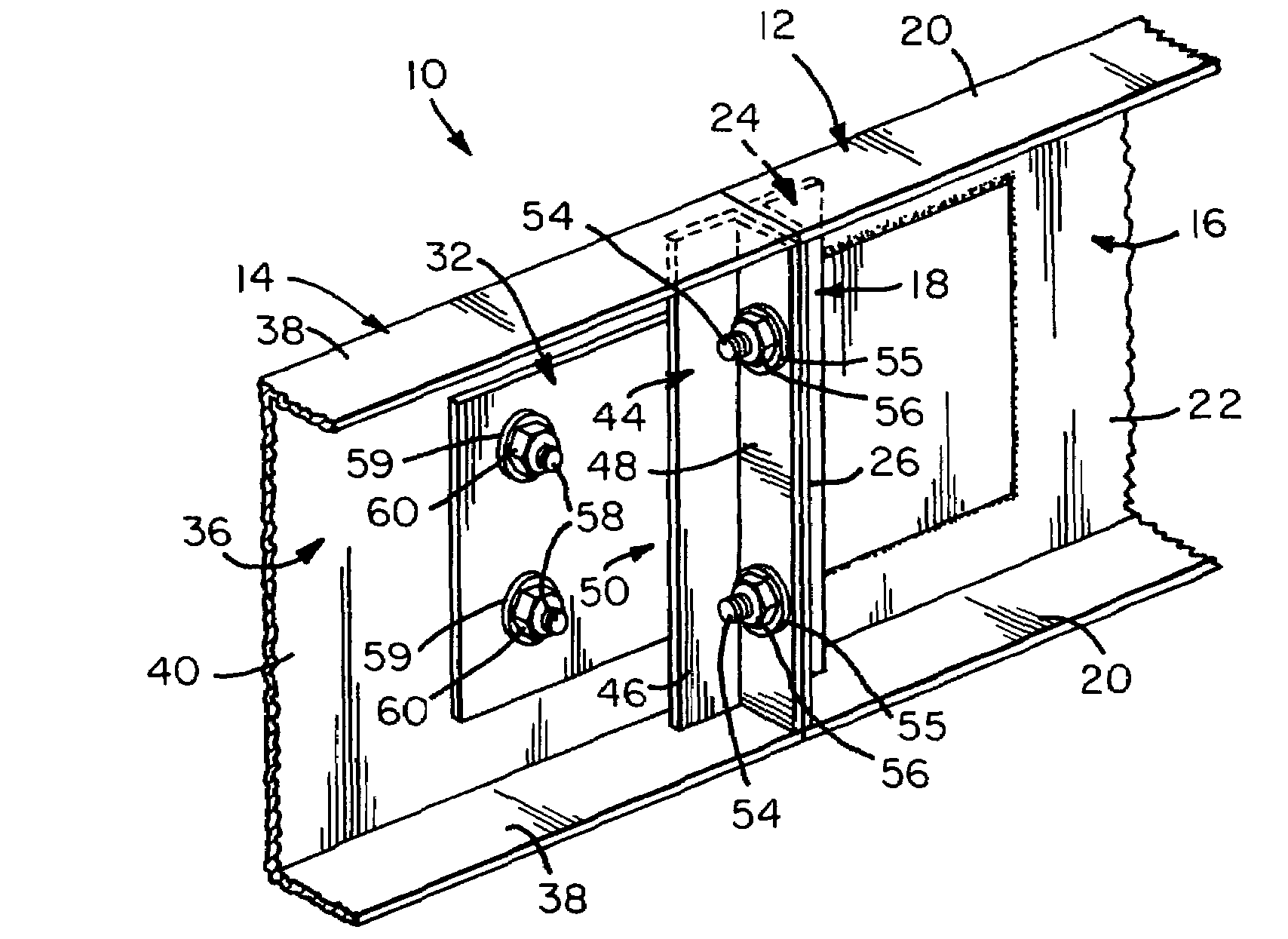
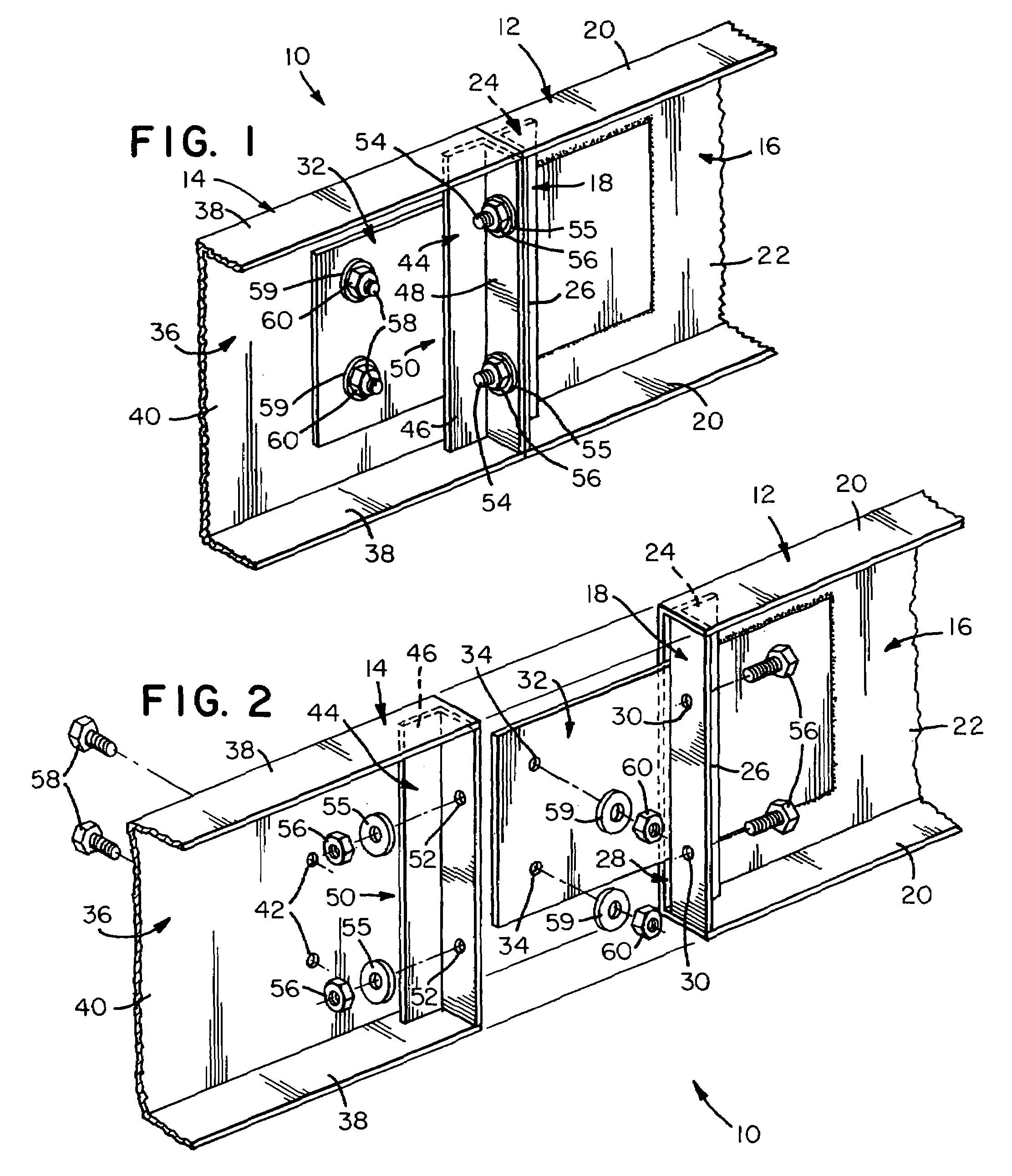
[0018]Referring now to FIGS. 1 and 2, a building member in accordance with the present invention is shown at 10. Building member 10 includes a male portion 12 and a female portion 14 that are mated end to end. Once mated, threaded fasteners are employed to selectively join male portion 10 and female portion 12 for an indefinite period.

[0019]Male portion 12 includes a beam 16 that is stiffened at one end by a bracket 18. Beam 16 has a pair of parallel wings 20 joined by a crosspiece 22 into a C-shaped arrangement. Bracket 18 is affixed between wings 20 and has a leg 24 and a leg 26 being joined in an L-shaped arrangement, i.e., joined at right angles. As shown, leg 24 is oriented parallel to crosspiece 22 and is spaced a short distance therefrom so as to define a slot 28 between leg 24 and crosspiece 22. Leg 26, however, extends away from slot 28, flush with the outer ends of wings 20, and is provided with a pair of apertures 30.

[0020]Male portion 12 features a tongue 32 that extends...


PUM


Abstract

A building member including a male portion and a female portion that are releasably connected together. The male portion includes a first beam having a first pair of wings joined together by a first crosspiece. A first bracket has first opposed ends each of which is affixed to a respective one of the first pair of wings so as to define a first slot between the first crosspiece and the first bracket. A tongue has an inner end that is affixed to the first crosspiece and an outer end, remote from the inner end, which extends through the first slot and outwardly from the first beam. The outer end of the tongue is provided with a first hole. The female portion, however, has a second beam that is adapted for end-to-end abutment with the first beam. The second beam has a second pair of wings that are joined together by a second crosspiece. The second crosspiece is provided with a second hole that is adapted for registration with the first hole in the tongue when the first beam and the second beam abut one another end-to-end. A second bracket having second opposed ends each of which is affixed to a respective one of the second pair of wings so as to define a second slot between the second crosspiece and the second bracket. The second slot is adapted to slidably receive the outer end of the tongue. A first threaded fastener extends through the first hole in the tongue and the second hole in the second crosspiece for releasably connecting the male portion to the female portion. A second threaded fastener penetrates the first bracket and the second bracket to reinforce the connection of the male portion to the female portion.

Description

FIELD OF THE INVENTION[0001]The present invention relates generally to static structures, e.g., buildings.BACKGROUND OF THE INVENTION[0002]Builders are confronted with significant challenges in offering high-quality construction at competitive prices. Fluctuations in lumber costs often work against builders in making profits for their efforts. In response to marketplace uncertainties, then, steel frame construction is emerging as a preferred way to construct buildings.[0003]More architects are now specifying steel framing for commercial and residential structures than in the past. They are attracted to the strength, termite resistance, and dimensional stability of metal. The varieties of steel dimensions and thicknesses has also grown beyond that of standard lumber, thus architects can now exhibit greater creativity in the design of buildings. Buildings with larger open spaces, longer floor spans and higher walls are the result of this combined creative effort.[0004]Buildings constr...

Claims


Application Information

Patent Timeline
Patent Type & Authority Patents(United States)
IPC IPC(8): F16B2/02
CPCE04B1/2403E04B2001/2415Y10T403/5786E04B2001/2457E04B2001/2448
Inventor HENDERSON, ANDREW G.
Owner ELEKSEN
Why Eureka
Try Eureka