
Constant voltage circuit

a constant voltage, circuit technology, applied in the direction of electric variable regulation, process and machine control, instruments, etc., can solve the problems of difficult design of low current consumption, inability to freely set voltage value, and non-negligible influence on manufacturing cost, etc., to achieve low current consumption, small circuit scale, and easy design

Active Publication Date: 2009-10-27
PANASONIC SEMICON SOLUTIONS CO LTD
View PDF6 Cites 2 Cited by
  • Summary
  • Abstract
  • Description
  • Claims
  • Application Information

AI Technical Summary

Benefits of technology

The present invention provides a constant voltage circuit that can generate a constant voltage output that is independent of temperature and has low current consumption. The circuit includes an output voltage control circuit, a temperature characteristic generating circuit, and an inverse temperature characteristic generating circuit. The inverse temperature characteristic generating circuit decreases the voltage output from the circuit and supplies it to the temperature characteristic generating circuit. The temperature characteristic generating circuit has a predetermined temperature characteristic that cancels the predetermined voltage characteristic by which the voltage output is decreased. The circuit also includes a differential amplification circuit that receives the voltage output and controls the voltage output. The inverse temperature characteristic generating circuit and the temperature characteristic generating circuit constrain a feedback loop, ensuring stable operation. The constant voltage circuit can be designed with low current consumption and reduced circuit scale.

Problems solved by technology

However, in the circuit of FIG. 11, the temperature-independent reference voltage VR5 has a fixed voltage value for each set of manufacturing conditions, i.e., the voltage value cannot be freely set.
Therefore, when the current consumption of the constant voltage circuit is reduced, the current consumption of the three circuits, i.e., the constant current source 54, the series circuit of the resistances R51 and R52, and the differential amplification circuit 52, needs to be reduced, and therefore, it is difficult to design low current consumption.
Therefore, an additional circuit configuration is required to design low current consumption, resulting in a non-negligible influence on manufacturing cost.

Method used


Image

  • Constant voltage circuit
  • Constant voltage circuit
  • Constant voltage circuit

Examples


first embodiment

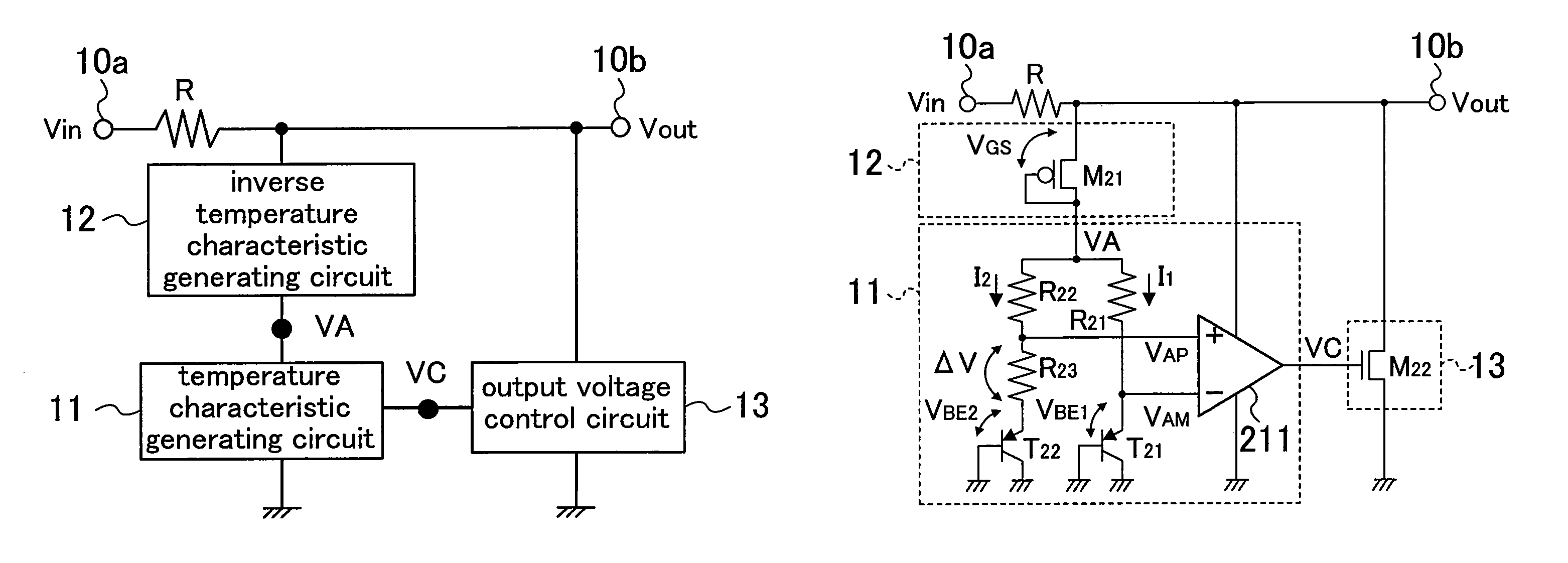
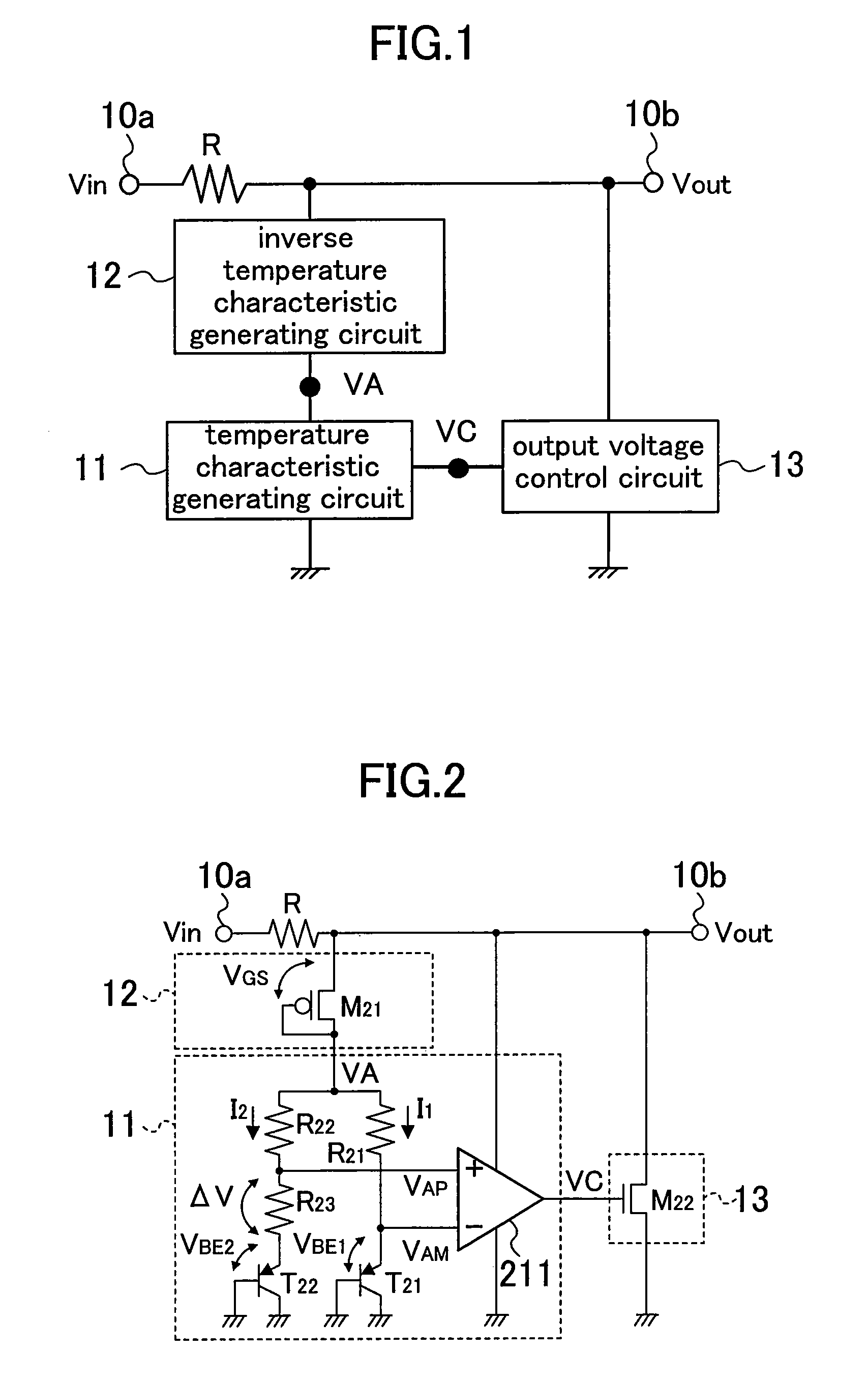
[0027]FIG. 1 is a block diagram showing a configuration of a constant voltage circuit according to a first embodiment of the present invention. The constant voltage circuit of FIG. 1 receives an input voltage Vin at an input terminal 10a, and outputs a constant voltage Vout from an output terminal 10b. The input terminal 10a and the output terminal 10b are connected to each other via a resistance R. A series circuit of a temperature characteristic generating circuit 11 and an inverse temperature characteristic generating circuit 12, and an output voltage control circuit 13 are each connected between the output terminal 10b and a ground. A voltage output end of the inverse temperature characteristic generating circuit 12 is connected to a voltage input end of the temperature characteristic generating circuit 11 at a terminal VA. The constant voltage Vout is input as a power supply voltage to the output voltage control circuit 13.

[0028]The inverse temperature characteristic generating...

second embodiment

[0061]FIG. 7 is a block diagram showing a configuration of a constant voltage circuit according to a second embodiment of the present invention. The constant voltage circuit of FIG. 7 outputs a constant voltage VR from an output terminal 30. A series circuit of a temperature characteristic generating circuit 31 and an inverse temperature characteristic generating circuit 32 is connected between the output terminal 30 and a ground. A voltage output end of the inverse temperature characteristic generating circuit 32 is connected to a voltage input end of the temperature characteristic generating circuit 31 at a terminal VA.

[0062]The inverse temperature characteristic generating circuit 32 generates a potential difference (VR−VA) between the constant voltage VR and a voltage VA, decreases the constant voltage VR by the voltage (VR−VA), and supplies the voltage VA via the voltage output end to the temperature characteristic generating circuit 31. The temperature characteristic generatin...


PUM


Abstract

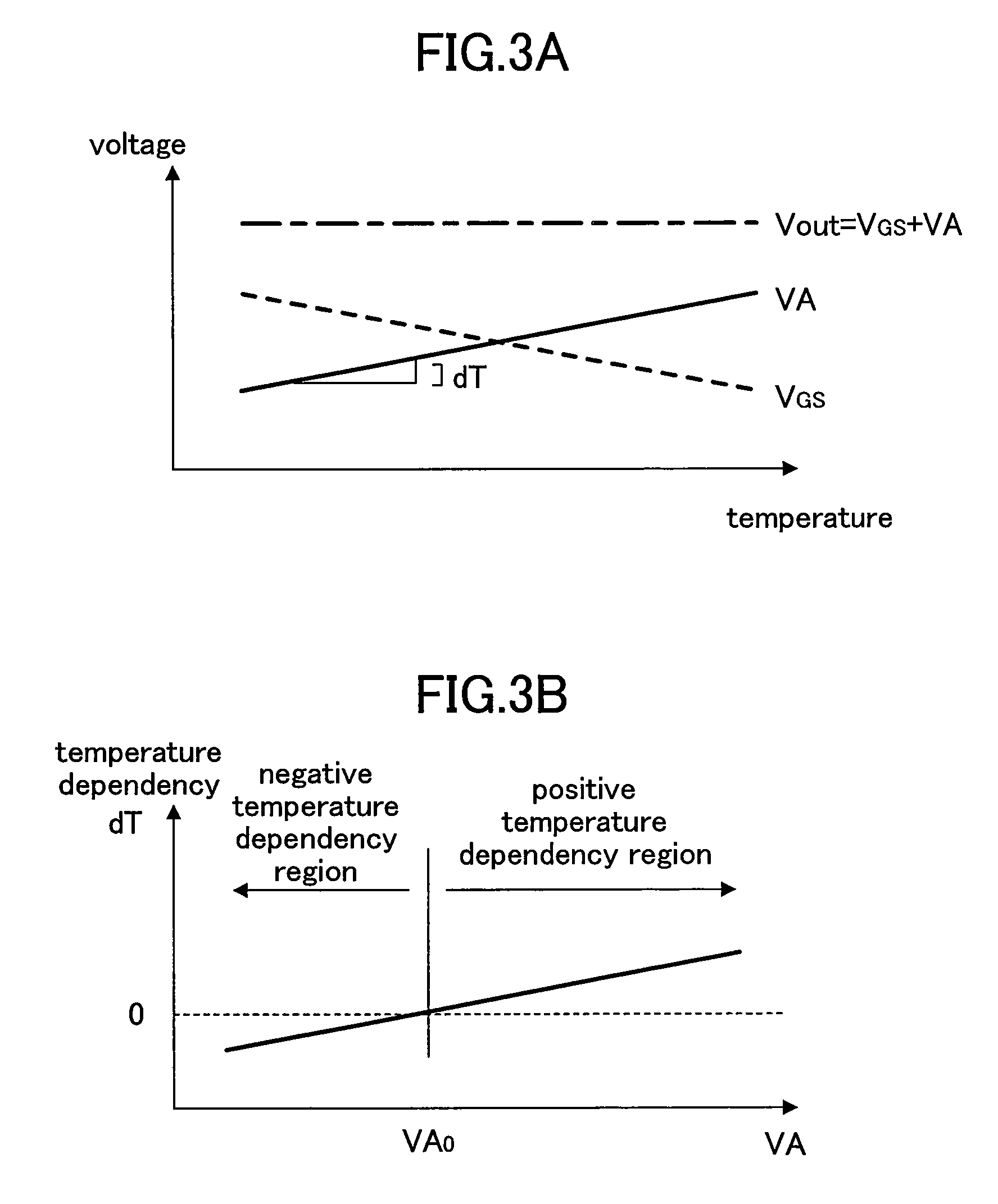
An inverse temperature characteristic generating circuit decreases an output voltage Vout by a voltage VGS, and supplies the resultant voltage as a voltage VA to a temperature characteristic generating circuit. The temperature characteristic generating circuit includes a differential amplification circuit that receives a terminal voltage VAP between resistances R22 and R23 and an emitter voltage VAM of a bipolar transistor T21, and outputs a control signal VC. When the terminal voltages VAP and VAM are equal to each other, an operation of a circuit is stable. The temperature characteristic of the voltage VA during the stable operation, and the temperature characteristic of the voltage VGS are inverse to each other and therefore cancel each other, so that the constant voltage Vout independent of temperature is output. In addition, the output terminal is not connected via a resistance to a ground, so that low current consumption can be easily achieved.

Description

CROSS REFERENCE TO RELATED APPLICATIONS[0001]This Non-provisional application claims priority under 35 U.S.C. §119(a) on Patent Application No. 2007-291170 filed in Japan on Nov. 8, 2007, the entire contents of which are hereby incorporated by reference.BACKGROUND OF THE INVENTION[0002]1. Field of the Invention[0003]The present invention relates to a constant voltage circuit for generating a constant voltage, and more particularly, to a technique for a circuit capable of generating a constant voltage independent of temperature.[0004]2. Description of the Related Art[0005]FIG. 11 is a diagram showing a configuration of a conventional constant voltage circuit capable of generating a constant voltage independent of temperature. A series circuit of a constant current source 54 and a reference voltage circuit 51, the source and drain of an NPN transistor 53, the power source and ground ends of a differential amplification circuit 52, and a series circuit of resistances R51 and R52, are e...

Claims


Application Information

Patent Timeline
Patent Type & Authority Patents(United States)
IPC IPC(8): G05F3/16
CPCG05F3/30G11C5/147
Inventor WADA, HIROFUMIINOUE, ATSUOMATSUNO, NORIAKI
Owner PANASONIC SEMICON SOLUTIONS CO LTD
Learn More