Energy metering system

a technology of energy metering and energy consumption, which is applied in the direction of line-transmission details, instruments, electric devices, etc., can solve the problems of undesirable measurement errors, unpredictable phase shift between the input channel and the inductive coupling of the transformer, and achieve the effect of little complexity

Active Publication Date: 2009-10-27
AUSTRIAMICROSYSTEMS AG
View PDF36 Cites 12 Cited by
  • Summary
  • Abstract
  • Description
  • Claims
  • Application Information

AI Technical Summary

Benefits of technology

[0010]The object of the present invention is to provide an energy consumption meter arrangement which can be integrated with littl

Problems solved by technology

One problem with such transformers, however, is the phase shift caused by the inductive coupling of the transformer.
Secondly, the phase shift also results between the signal representing the current and that representing the voltage, however.
This results in undesirable measurement errors during the multiplication of voltage and current, however.
The described problem is further intensified, in addition, by the fact that, even when in each case one transformer-based transfer arr

Method used


Image

  • Energy metering system
  • Energy metering system

Examples


Embodiment Construction

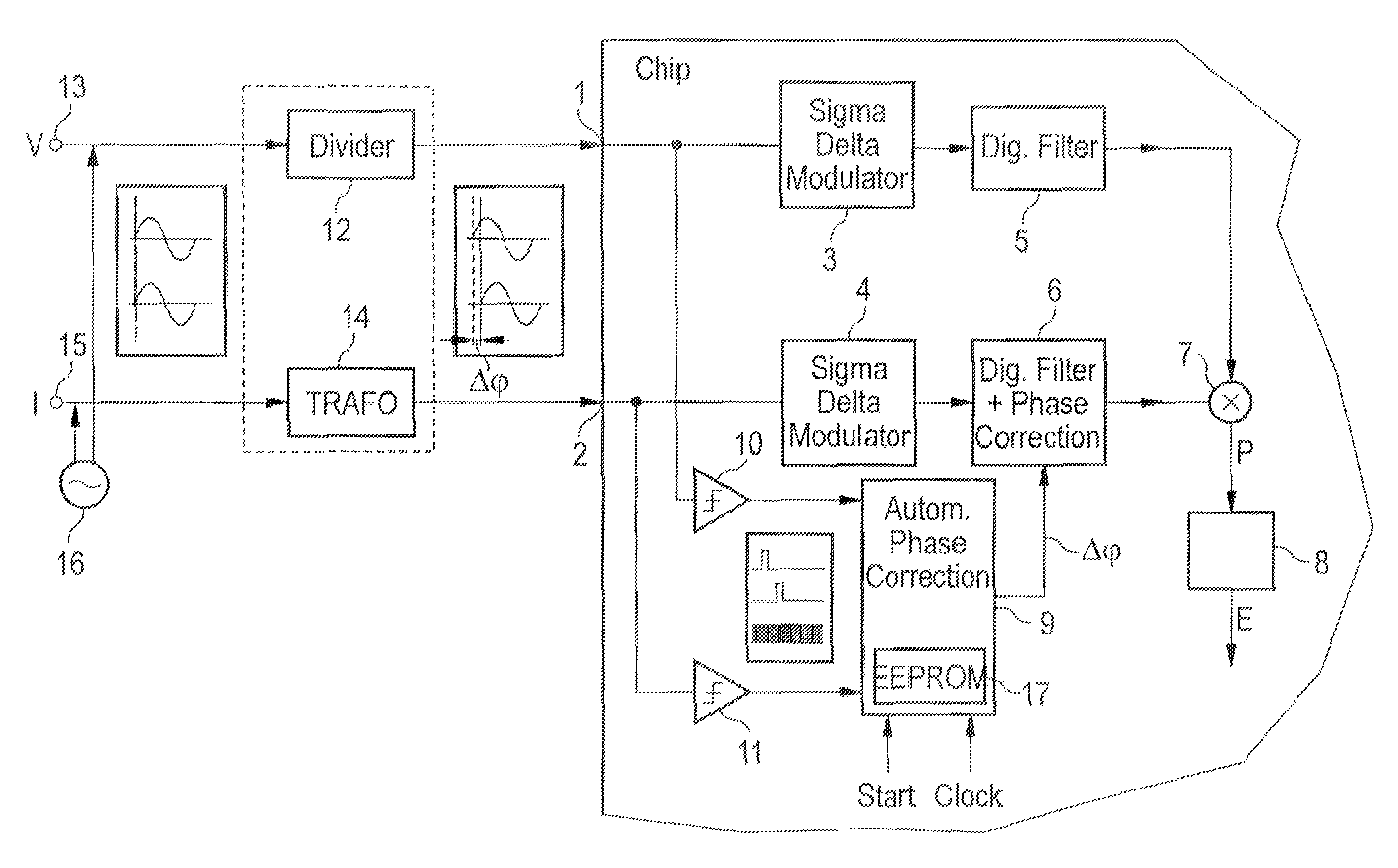
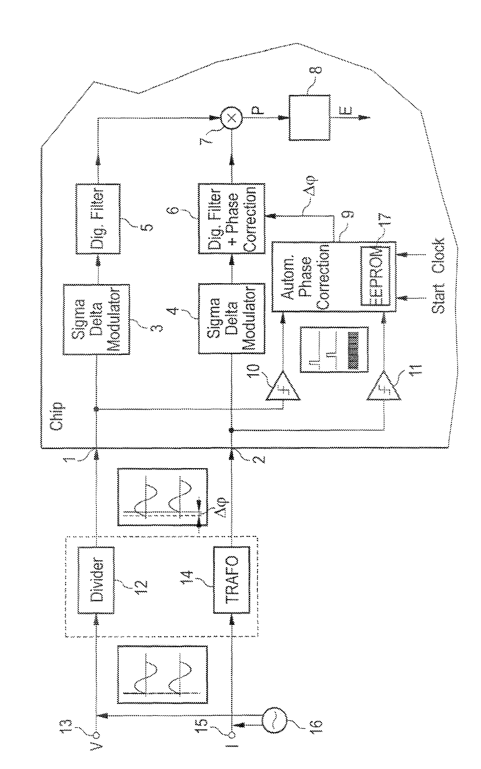
[0041]The FIGURE shows an energy consumption meter arrangement having a first input 1 and a second input 2. The first input 1 is designed for feeding a signal derived from an electrical voltage V. The second input 2 is designed for feeding a signal derived from an electrical current I. In this case, the electrical voltage V and the electrical current U are based on the same signal. The input of a first analog-to-digital converter 3 is connected to the first input 1. The input of a second analog-to-digital converter 4 is connected to the second input 2. The analog-to-digital converters 3, 4 are each in the form of sigma-delta modulators. The output of the first analog-to-digital converter 3 is connected to the input of a multiplier 7 via a first digital filter 5. The output of the second analog-to-digital converter 4 is connected to a further input of the multiplier 7 via a second digital filter 6. The second digital filter 6 comprises a phase correction block. An integrator 8 is con...


PUM


Abstract

An energy consumption meter includes a first input for providing a first input signal derived from a voltage, a first analog-to-digital (A/D) converter electrically connected to the first input to generate a first output signal based on the first input signal, a second input for providing a second input signal derived from a current, a second A/D converter electrically connected to the second input to generate a second output signal based on the second input signal, a multiplier to combine signals corresponding to the first and second output signals, and a phase evaluation block having two inputs that are electrically connected to the first input and to the second input. The phase evaluation block measures a phase difference that corresponds to a phase difference between the first input signal and the second input signal. A phase correction block corrects for the phase difference in one of the first output signal and the second output signal.

Description

TECHNICAL FIELD[0001]The present invention relates to an energy consumption meter arrangement.BACKGROUND[0002]Energy consumption meters are used for detecting consumed or generated electrical energy. Such energy consumption meters are also referred to as electricity meters or kilowatt hour meters.[0003]In the case of electronically operating energy consumption meters, voltage and current are normally detected, digitized and multiplied by one another. After the multiplication, the instantaneous electrical power is provided. If this electrical power is integrated or accumulated over time, a signal is obtained which is a measure of the electrical energy generated or consumed in a specific period of time.[0004]In order to obtain signals which are proportional to electrical voltage and to electrical current, voltage dividers, voltage transformers, current transformers or other means for coupling out signals can be used.[0005]In many applications it is necessary to provide DC isolation at...

Claims


Application Information

Patent Timeline
IPC IPC(8): G01R21/00G01R7/00G01R21/133G01R35/04
CPCG01R21/133H04B3/03G01R35/04
Inventor FRITZ, GERHARDSCHMALZL, ERWIN
Owner AUSTRIAMICROSYSTEMS AG
Why Eureka
Try Eureka