
Latency control circuit and method thereof and an auto-precharge control circuit and method thereof

a control circuit and control circuit technology, applied in the direction of information storage, static storage, digital storage, etc., can solve the problems of increasing increasing the complexity of routing, and relatively large current consumption, so as to reduce the number of registers, reduce the area occupied by the register, and reduce the loading of the internal clock signal

Inactive Publication Date: 2009-10-27
SAMSUNG ELECTRONICS CO LTD
View PDF26 Cites 49 Cited by
  • Summary
  • Abstract
  • Description
  • Claims
  • Application Information

AI Technical Summary

Benefits of technology

The proposed solution decreases the number of registers required for latency and auto-precharge control, lowering current consumption and layout area, and improves operational efficiency by optimizing register usage and command timing in semiconductor memory devices.

Problems solved by technology

Because many flip-flops may be included in the conventional latency control circuit 1500, a current consumption may be relatively large.
If the number of registers increases above a threshold (e.g., 200 registers), an area occupied by the registers may increase and routing may become increasingly complicated.
Accordingly, as the size of latency control circuit 1500 increases, a line or conductive path of a clock signal input to the latency control circuit 1500 may become longer, thereby increasing a delay time of the clock signal.
As a result, a power consumption or current consumption may be increased.

Method used


Image

  • Latency control circuit and method thereof and an auto-precharge control circuit and method thereof
  • Latency control circuit and method thereof and an auto-precharge control circuit and method thereof
  • Latency control circuit and method thereof and an auto-precharge control circuit and method thereof

Examples


Embodiment Construction

[0056]Detailed illustrative example embodiments of the present invention are disclosed herein. However, specific structural and functional details disclosed herein are merely representative for purposes of describing example embodiments of the present invention. Example embodiments of the present invention may, however, be embodied in many alternate forms and should not be construed as limited to the embodiments set forth herein.

[0057]Accordingly, while example embodiments of the invention are susceptible to various modifications and alternative forms, specific embodiments thereof are shown by way of example in the drawings and will herein be described in detail. It should be understood, however, that there is no intent to limit example embodiments of the invention to the particular forms disclosed, but conversely, example embodiments of the invention are to cover all modifications, equivalents, and alternatives falling within the spirit and scope of the invention. Like numbers may ...


PUM


Abstract

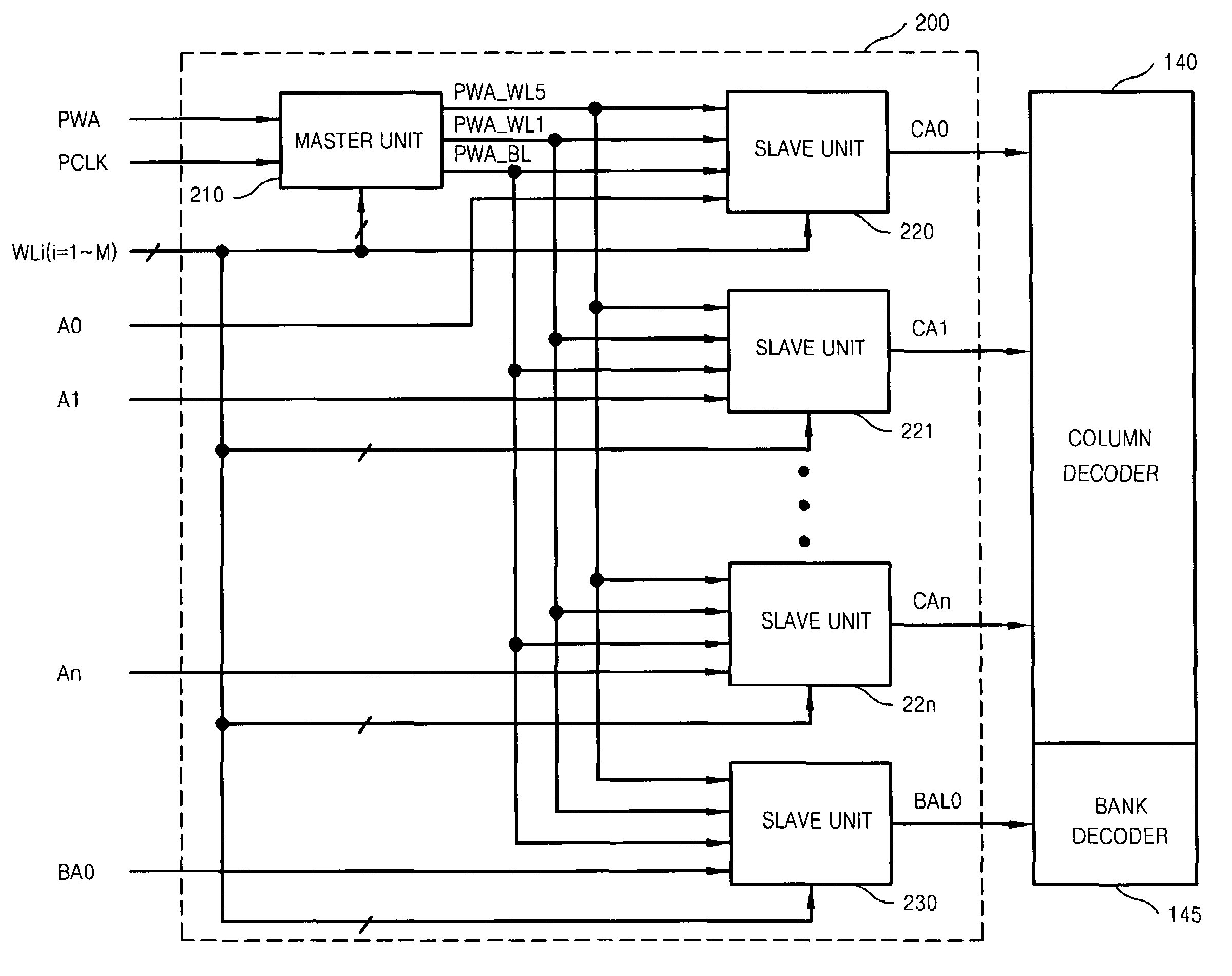
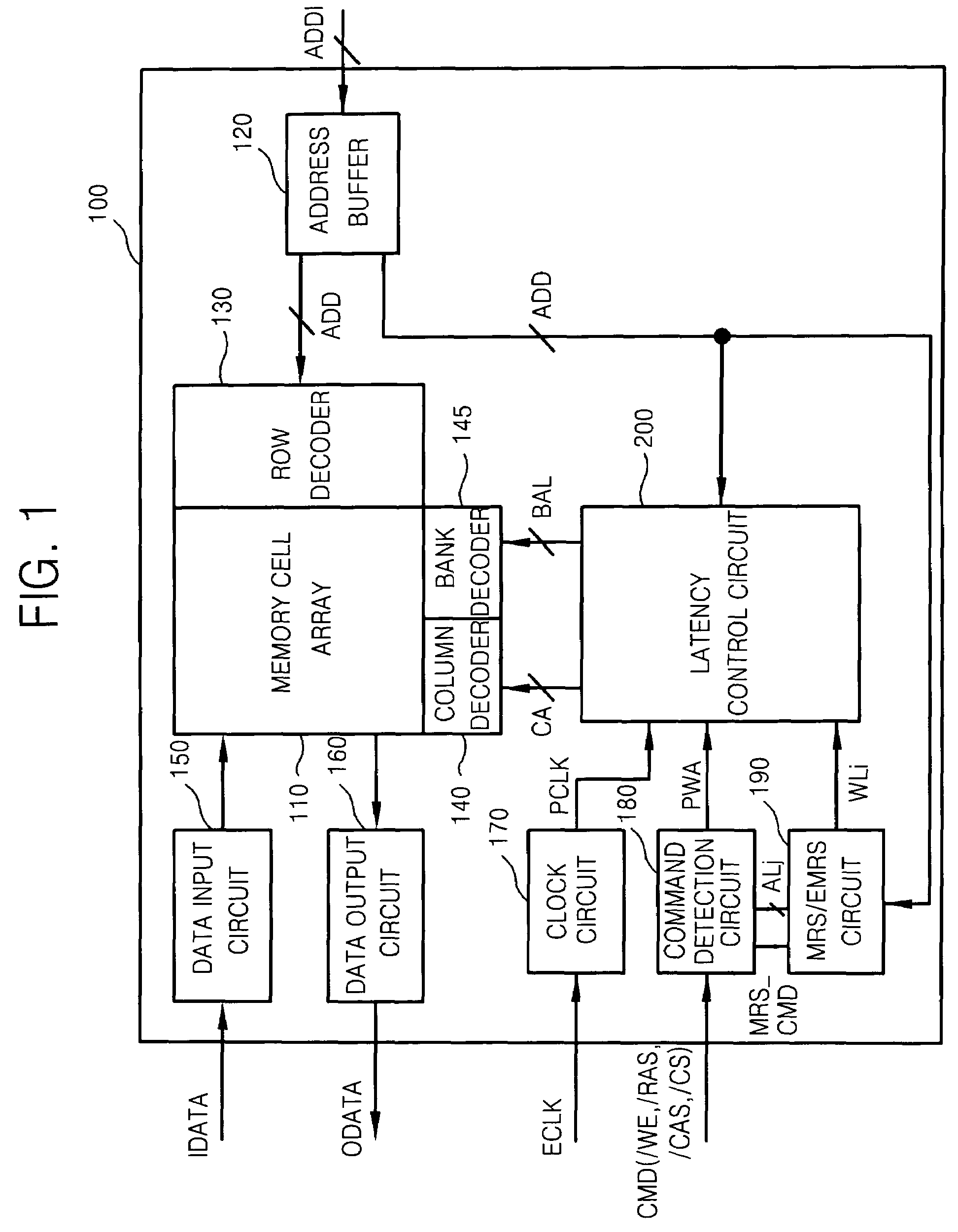
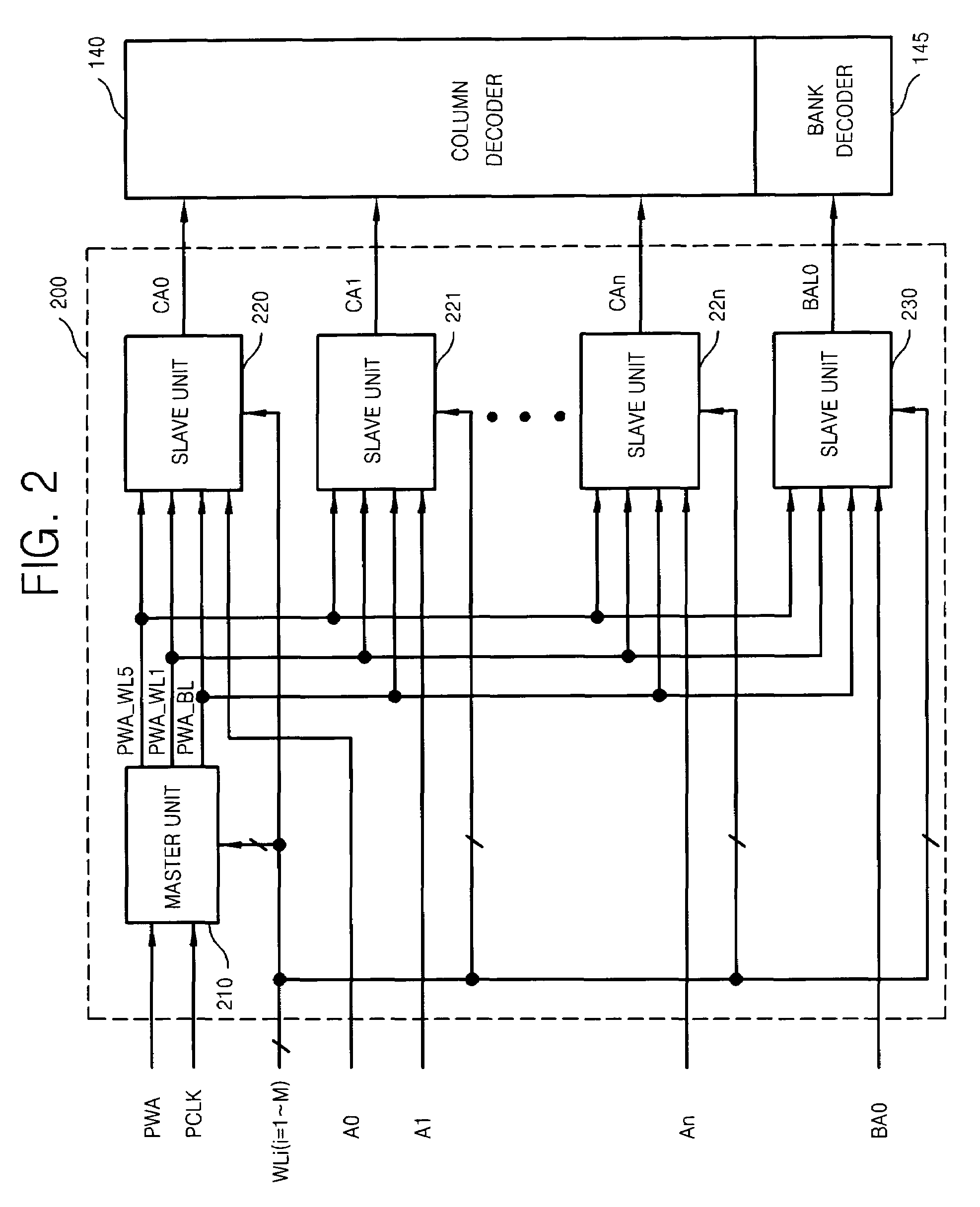
A latency control circuit and method thereof and auto-precharge control circuit and method thereof are provided. The example latency control circuit may include a master unit activating at least one master signal based on a reference signal and an internal clock signal and a plurality of slave units receiving the at least one master signal, each of the plurality of slave units receiving a plurality of signals and outputting an output signal based at least in part upon one of the received plurality of signals. The example method of latency control may include receiving at least one master signal, the received at least one master signal activated based on a reference signal and an internal clock signal and receiving a plurality of signals and outputting an output signal based at least in part upon one of the received plurality of signals and latency information. The example auto-precharge control circuit may include a precharge command delay unit generating a plurality of first precharge command delay signals in response to an internal clock signal and a write auto-precharge command signal, at least one bank address delay unit outputting a delayed bank address signal and a precharge main signal generator outputting a precharge main signal to banks based on the delayed bank address signal. The method of performing a precharging operation with the auto-precharge control circuit may include delaying a bank address signal based on a minimum time interval between executed memory commands and outputting a precharge main signal to one or more memory banks based on the delayed bank address signal.

Description

[0001]This application claims the priority of Korean Patent Application No. 10-2005-0111027, filed on Nov. 19, 2005, Korean Patent Application No. 10-2006-0039897, filed on May 3, 2006, and Korean Patent Application No. 10-2006-0063463, filed on Jul. 6, 2006, in the Korean Intellectual Property Office, the contents of which are incorporated herein in their entirety by reference.BACKGROUND OF THE INVENTION[0002]1. Field of the Invention[0003]Example embodiments of the present invention relate generally to a latency control circuit and method thereof and an auto-precharge control circuit, and more particularly to a latency controlling circuit and a method of controlling latency and an auto-precharge control circuit.[0004]2. Description of the Related Art[0005]Data may be input to and / or output from a synchronous semiconductor device in synchronization with an external clock signal. Double data rate (DDR) dynamic random access memory (DRAM) may use a write latency (WL) scheme and / or an...

Claims


Application Information

Patent Timeline
Patent Type & Authority Patents(United States)
IPC IPC(8): G11C8/00
CPCG11C7/1027G11C7/1045G11C7/1066G11C7/12G11C11/4094G11C8/10G11C8/12G11C11/4076G11C7/22
Inventor KIM, JOUNG-YEALJANG, SEONG-JINKIM, KYOUNG-HOBANG, SAM-YOUNGOH, REUM
Owner SAMSUNG ELECTRONICS CO LTD
Learn More