Laser system using ultra-short laser pulses

Active Publication Date: 2009-10-27
BOARD OF TRUSTEES OPERATING MICHIGAN STATE UNIV
View PDF93 Cites 40 Cited by
  • Summary
  • Abstract
  • Description
  • Claims
  • Application Information

AI Technical Summary

Benefits of technology

[0008]The present invention also improves the encoding-decoding functionality of pulses by adding considerably more information to each pulse by obtaining the entire phase function directly from a phase scan. Intrapulse interferences of the present invention causes self separation (for example, inherent communication signal routing address differentiation) thereby allowing use of inexpensive receivers in an asynchronous manner, in other words, without the need for synchronous detection such as by traditional autocorrelation or interferometers. The control of nonlinear optical processes using multiphoton intrapulse interference can be applied in diverse fields such as photochemistry, communications, and medicine.

Problems solved by technology

Commercially practical femtosecond lasers have been unavailable until recently.
For example, lasers which can generate 10 femtosecond or less laser pulse durations have traditionally been extremely expensive, required unrealistically high electrical energy consumption (for extensive cooling, by way of example) and depended on laser dyes that had to be replenished every month thereby leading to commercial impracticality.
The efficiency of sub-10 femtosecond lasers was not practical until the year 2000 because of the prior need for dyes and flash lamps instead of YAG and Ti: Sapphire crystals pumped by light or laser emitting diodes.
Ultrashort pulses are prone to suffer phase distortions as they propagate through or reflect from optics because of their broad bandwidth.
These shaped pulses require a very large data set and in many cases, complex learning calculations for determining the pulse shaping characteristics for a particular application.
Since the variation shape of the possible pulse shapes is huge, scanning the entire parameter space is impossible and as such the optimized pulse shape could not have been predicted by theory.
This dataset is extremely large, therefore, while in principle, the field exists to achieve the desired photonic transformation or excitation, finding it is a great challenge.

Method used


Image

  • Laser system using ultra-short laser pulses
  • Laser system using ultra-short laser pulses
  • Laser system using ultra-short laser pulses

Examples


Embodiment Construction

[0035]The following description of the preferred embodiments is merely exemplary in nature and is in no way intended to limit the invention, its application, or uses.

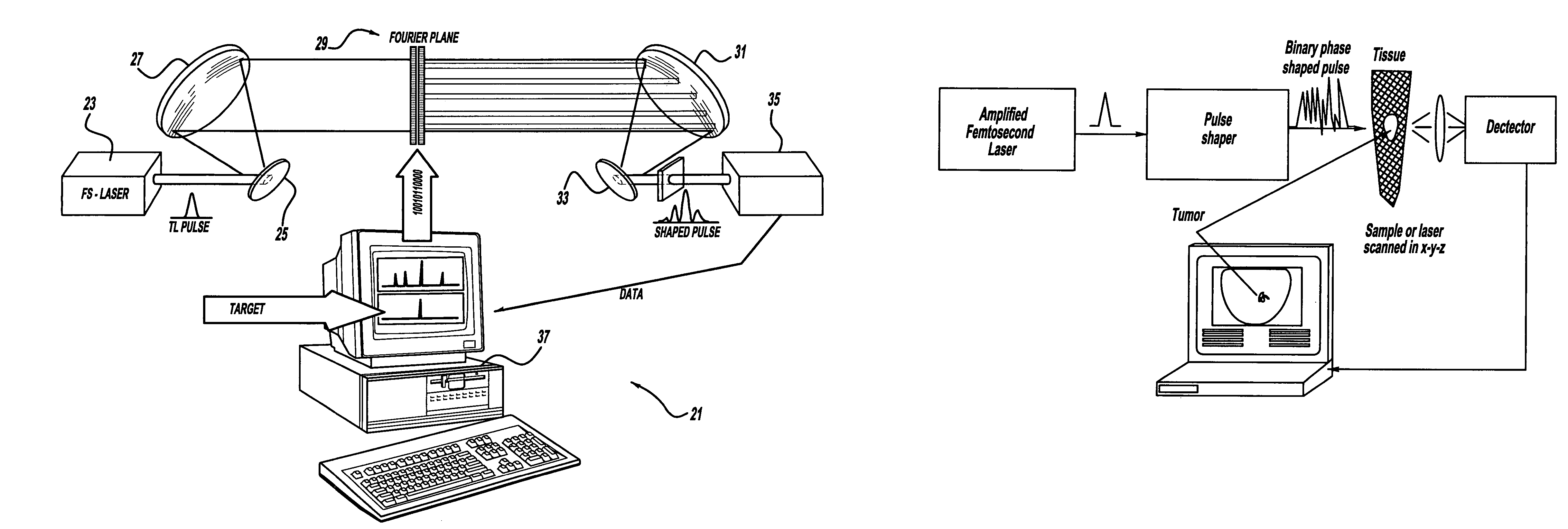
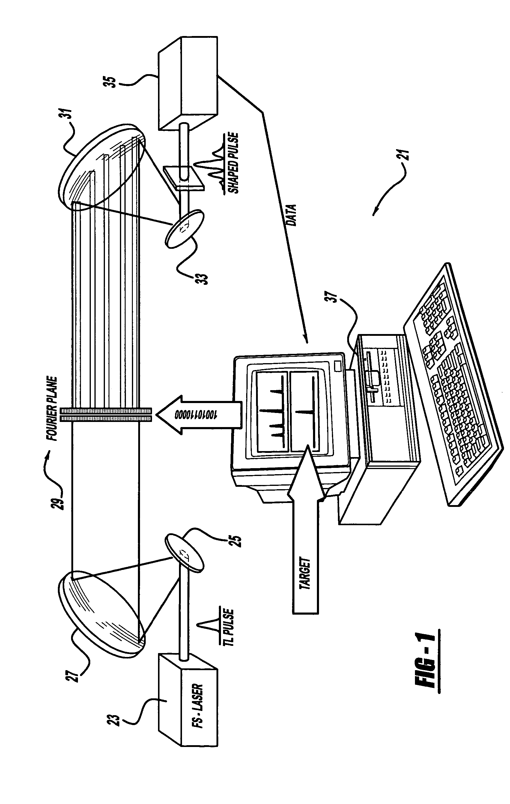
[0036]The present invention provides methods and apparatus for a laser system using ultra short pulses. Pulse shaping essentially involves control over the amplitude, phase, frequency and / or inter-pulse separation. Complex pulse shaping aims to control one or more of the above-mentioned parameters in a programmable manner, such that the user has complete control. In other words, complex pulse shaping allows generation of complicated ultrafast optical waveforms according to user specification.

[0037]Coherent control is the ability to control the dynamics at various stages of a process as it evolves under the effect of a coherent source. Many of the frequencies constituting the ultrafast pulse can simultaneously excite many coherent transitions to the excited states, and a capability to manipulate them with the shaped puls...


PUM


Abstract

A laser system using ultrashort laser pulses is provided. In another aspect of the present invention, the system includes a laser, pulse shaper and detection device. A further aspect of the present invention employs a femtosecond laser and binary pulse shaping (BPS). Still another aspect of the present invention uses a laser beam pulse, a pulse shaper and a SHG crystal.

Description

CROSS REFERENCE TO RELATED APPLICATIONS[0001]This is a continuation-in-part of U.S. patent application Ser. No. 10 / 265,211, filed Oct. 4, 2002 now U.S. Pat. No. 7,450,618, which is a continuation-in-part of PCT Serial No. PCT / US02 / 02548, filed on Jan. 28, 2002, which claims priority to U.S. provisional application Ser. No. 60 / 265,133, filed Jan. 30, 2001, which are all incorporated by reference herein.STATEMENT OF GOVERNMENT INTEREST[0002]A portion of this invention was made with U.S. Government support under Contract No. DE-FG02-01ER15143 awarded by the Department of Energy. The Government may have certain rights in this invention.BACKGROUND[0003]The present invention generally relates to a laser system and more particularly to a laser system using ultra short laser pulses and a pulse shaper.[0004]Commercially practical femtosecond lasers have been unavailable until recently. For example, lasers which can generate 10 femtosecond or less laser pulse durations have traditionally been...

Claims


Application Information

Patent Timeline
IPC IPC(8): H01S3/13G01B9/02G01N21/47H01J49/16H01S3/00H01S3/098H01S3/10
CPCG01N21/4795G01B9/02014G01B9/02091H01S3/0057
Inventor DANTUS, MARCOSLOZOVOY, VADIM V.COMSTOCK, MATTHEW
Owner BOARD OF TRUSTEES OPERATING MICHIGAN STATE UNIV
Why Eureka
Try Eureka