Particle detection sensor, method for manufacturing particle detection sensor, and method for detecting particle using particle detection sensor

a technology of particle detection and sensor, which is applied in the direction of instruments, specific gravity measurement, and mechanical means, etc., can solve the problems of long measurement time and large devices, and achieve the effect of short measurement tim

Inactive Publication Date: 2009-11-03
SEMICON ENERGY LAB CO LTD +1
View PDF19 Cites 12 Cited by
  • Summary
  • Abstract
  • Description
  • Claims
  • Application Information

AI Technical Summary

Benefits of technology

[0008]Correspondingly, it is an object of the present invention to provide a sensor with which particles floating in the air can be easily detected. Further, it is another object of the invention to provide such a particle detection sensor at low cost.
[0012]A particle detection sensor of the invention has intake unit for making a detection object adsorbed to a detection hole. In order to make the detection object be adsorbed, reduced pressure is preferable. Under reduced pressure, the adsorption ratio of the detection object can be increased and the accuracy of capturing the detection object can be increased.
[0034]The invention can provide a particle detection sensor using a microstructure formed of a thin film material over an insulating substrate. The invention using a microstructure formed of a thin film material without using an optical method is a compact (small size) particle detection sensor of which measurement time is short.
[0035]In accordance with the present invention, since a particle detection sensor is formed using a thin film material over an insulating substrate, a low-cost particle detection sensor can be provided.

Problems solved by technology

Since a conventional pollen sensor performs detection in an optical manner, there has been a problem that long time is required for the measurement.
Further, it has also been a problem that a light source or a detector is required to be used, and the device has become larger.

Method used


Image

  • Particle detection sensor, method for manufacturing particle detection sensor, and method for detecting particle using particle detection sensor
  • Particle detection sensor, method for manufacturing particle detection sensor, and method for detecting particle using particle detection sensor
  • Particle detection sensor, method for manufacturing particle detection sensor, and method for detecting particle using particle detection sensor

Examples


embodiment modes

[0054]Embodiment Modes will be described below with reference to the drawings. However, the present invention is not limited to the description below because it is easily understood by those skilled in the art that the modes and details can be variously modified without departing from the sprit and scope of the invention. Therefore, the present invention should not be construed as being limited thereto. Incidentally, in the descriptions for explaining the structure of the invention with reference to drawings, the same reference numerals denoting the same parts or parts having the same functions are commonly used in the different drawings.

embodiment mode 1

[0055]In this embodiment mode, a structure of a detection unit of a particle detection sensor will be described.

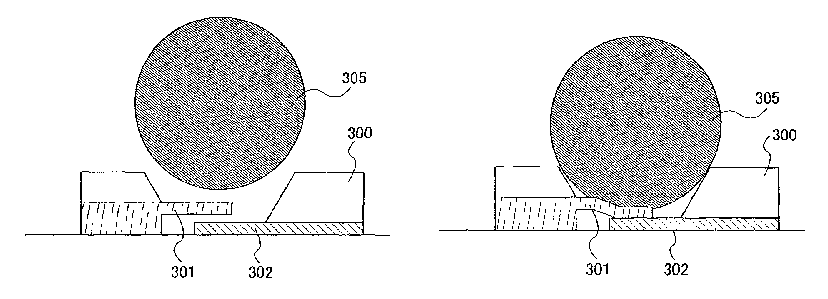
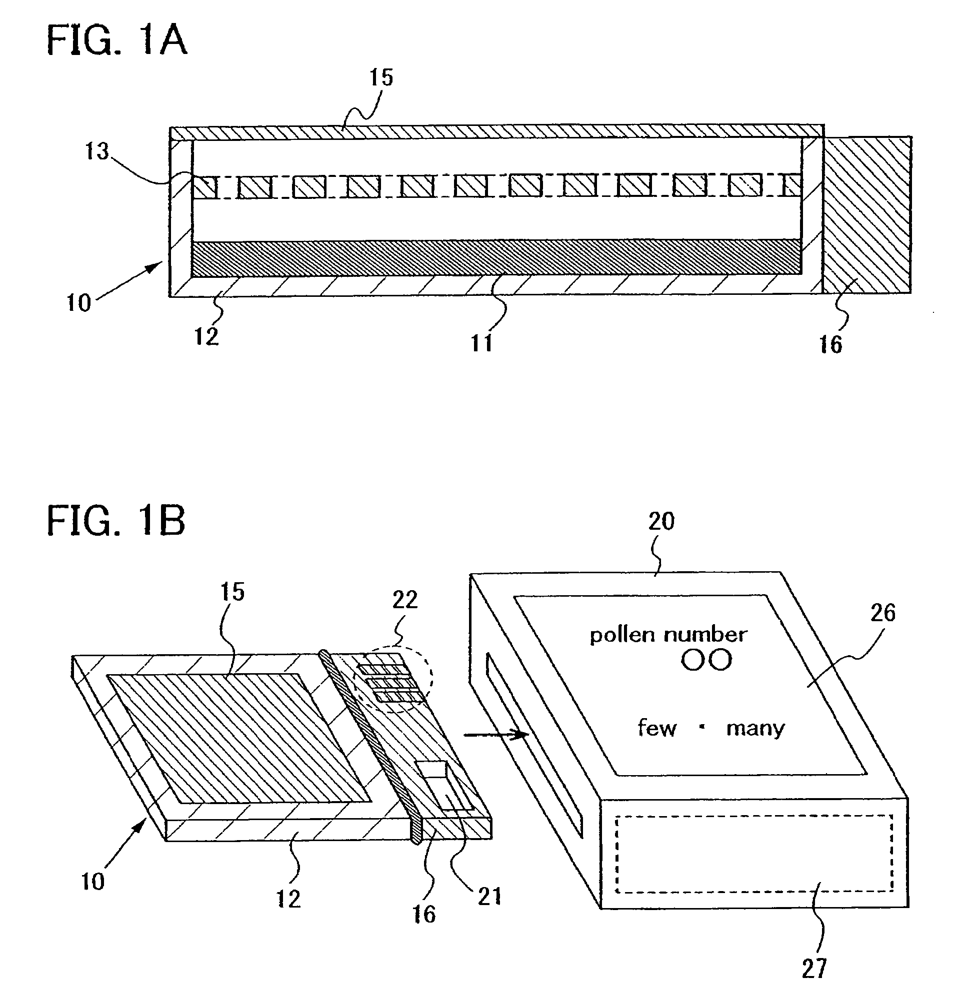
[0056]FIG. 1A shows a cross-sectional view of a detection unit. In a detection unit 10, a detector 11 is provided in a receptacle 12 and a filter 13 is provided above the detector 11. A detection object can be detected using the detector 11. Hereupon, a detection hole is provided on the detector 11, and the detection is preferably conducted when the detection object is adsorbed to the detection hole. Further, articles which are larger than the detection object are prevented from mixing in with the use of the filter 13. In order to increase detection accuracy, the detection unit is preferably used in such a manner that a cover 15 is provided on a top face of the receptacle 12 and the cover 15 is removed immediately before the use. Further, the cover 15 is preferably attached also in order to prevent attachment of foreign matter when carried and prevent a sensor area from br...

embodiment mode 2

[0065]In this embodiment mode, a case of providing a wireless communication function on a particle detection sensor, for example on an intake unit so as to perform wireless communication will be described.

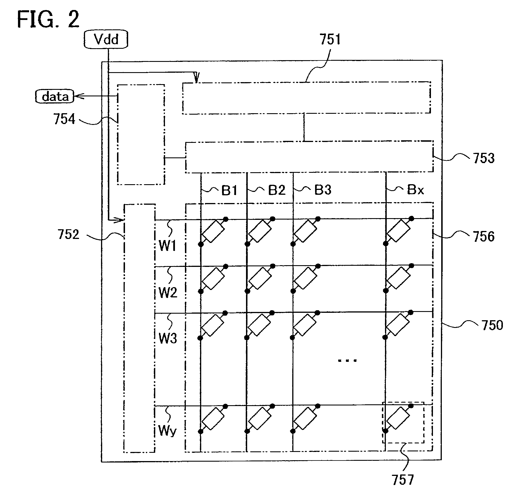
[0066]As shown in FIG. 11A, in the case of supplying power wirelessly, the intake unit 20 includes a resonant circuit 702 having an antenna and a resonant capacitor, a power circuit 703, a clock generation circuit 704, a demodulation circuit 705, a control circuit 706, and a modulation circuit 709. Naturally, the intake unit 20 includes an intake means 708 (for example, a pump or the like) and a power supply 713 for intake. Further, the intake unit 20 is provided with an external sensor circuit 707. The sensor circuit 707 is provided on the detection unit 10.

[0067]The resonant circuit 702 receives an electric wave transmitted by an antenna 710, and generates an AC signal at both ends of the antenna. The generation AC signal includes information such as instructions transmitted by t...


PUM

PropertyMeasurementUnit
thicknessaaaaaaaaaa
thicknessaaaaaaaaaa
thicknessaaaaaaaaaa

Abstract

A compact sensor with which particles floating in the air can be easily detected. A sensor having a microstructure which detects a detection object by contact is used. A microstructure has an opening to be a detection hole corresponding to the size of a detection object, and a pair of electrodes having a bridge structure are provided thereabove or thereunder so as to partially contact with each other.

Description

BACKGROUND OF THE INVENTION[0001]1. Field of the Invention[0002]The preset invention relates to a sensor for detecting particles through a MEMS technology, a method for manufacturing such a sensor, and a method for detecting particles using a particle detection sensor.[0003]2. Description of the Related Art[0004]Research on micromechanical systems called MEMS has been actively advanced. MEMS (Micro Electro Mechanical System) is an abbreviation of a microelectromechanical system, and also simply called a micromachine. A micromachine means a microdevice formed by integrating a “movable microstructure with a three-dimensional structures” using a semiconductor micromachining technique. A microstructure may function as a switch, a variable capacitor, an actuator, or the like. Such a micromachine is formed from a silicon wafer, and is used as an inertial force sensor (Reference 1: Japanese Patent Application Publication No. 2003-329704).[0005]As an example of a sensor used at present, a p...

Claims


Application Information

Patent Timeline
Patent Type & Authority Patents(United States)
IPC IPC(8): G01N27/04G01N15/02
CPCG01N15/1056G01N15/1031
Inventor YAMAGUCHI, MAYUMIIZUMI, KONAMITATEISHI, FUMINORI
Owner SEMICON ENERGY LAB CO LTD
Why Eureka
Try Eureka