Light-source fixing structure for backlight module

a technology of fixing structure and backlight module, which is applied in the field of backlight module, can solve the problems of lower production cost, reduce production cost, and reduce replacement time, and achieve the effects of reducing production cost, reducing replacement time, and easy replacemen

Inactive Publication Date: 2009-11-03
CHUNGHWA PICTURE TUBES LTD
View PDF6 Cites 29 Cited by
  • Summary
  • Abstract
  • Description
  • Claims
  • Application Information

AI Technical Summary

Benefits of technology

[0007]One object of the present invention is to provide a light-source fixing structure for the backlight module such that the light bar producing point light can be substituted for the lamp and can be arranged within the cover to provide the edge light to the light guide plate. Because of coating the reflection on the cover is unnecessary, the production cost will be lower down.
[0008]One object of the present invention is to provide a light-source fixing structure for the backlight module. The groove can be formed by ribbing the cover and the light bar can be slid in / out along the groove so that the groove and the light bar can cooperate to form a changeable mechanism. Hence, when the light bar was damaged, the light bar can be replaced easily by sliding out from the groove. Owing to these, the replace time will be reduced and the production cost will be lower down.
[0009]One object of the present invention is further to provide a light-source fixing structure for the backlight module such that the substrate made of metal having high conductivity can cooperate with the cover made of metal having good heat-sinking capability to lower the temperature around the backlight module. Furthermore, the cover can enhance the assembly structure, fix the light bar, and increase the reliability of the backlight module.

Problems solved by technology

Because of coating the reflection on the cover is unnecessary, the production cost will be lower down.

Method used


Image

  • Light-source fixing structure for backlight module
  • Light-source fixing structure for backlight module
  • Light-source fixing structure for backlight module

Examples


first embodiment

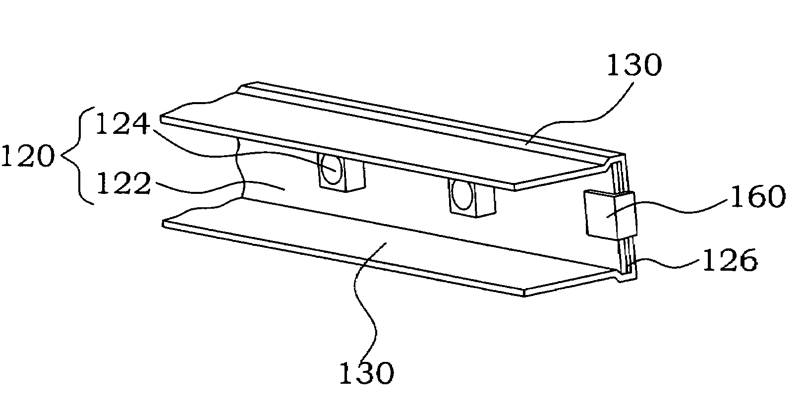
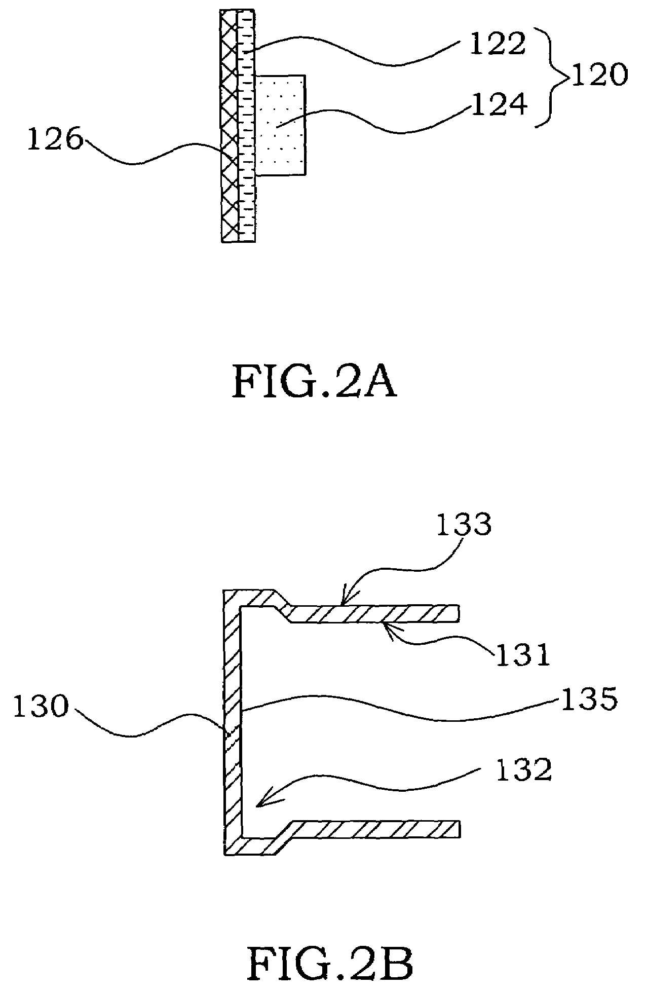
[0024]Referring to FIG. 2A, FIG. 2A is a schematic cross-sectional view of the architecture of the light bar for the backlight module of the first embodiment in accordance with the present invention. Such as shown in FIG. 2A, the light bar 120 includes a substrate 122, for example a printed circuit board, and at least a light emitting diode 124 fixed on the substrate 122 by utilizing the conventional technology method. In one embodiment, the light bar 120 further includes a metal substrate 126 having good heat conductivity, such as aluminum (Al) or copper (Cu), adhered under the substrate 122 so as to increase the heat-sinking capability. Wherein the position of the light emitting diodes 124 attached on the substrate 122 is not limited. Besides, refer to FIG. 2B, the cover 130 includes the metal having good heat-sinking capability, such as Al, and the interior surface 131 thereof has a groove 132. Wherein the groove 132 has a surface 135 facing toward to the light-incident surface o...

fifth embodiment

[0027]Continuously, please refer to FIG. 5, FIG. 5 is a cross-sectional view of the architecture of the backlight module of the fifth embodiment, in accordance with the present invention. The backlight module 100 includes a light guide plate 110, the light bar 120 and the cover 130 of the abovementioned embodiment. Wherein the light guide plate 110 has a light-incident surface; the groove 132 of the cover 130 having a surface 135 facing toward to the light-incident surface 112 of the light guide plate 110, wherein the light bar 120 can be arranged upon the surface 135 of the groove 132. The light bar 120 held by the frame 140 is arranged on the side edge of the light guide plate 110 so as to provide a side light to the light-incident surface 112 of the light guide plate 110. Such as described in the aforementioned embodiments, the light bar 120 includes a substrate 122, for example a printed circuit board, and a plurality of light emitting diodes 124 fixed on the substrate 122 by us...


PUM


Abstract

A light-source fixing structure for the backlight module is disclosed. The light-source fixing structure includes: a light guide plate provided with a light-incident surface; a cover having a groove, wherein the groove has a surface facing toward to the light-incident surface of the light guide plate; a light bar arranged upon the surface of the groove. The light bar may be replaced easily by sliding out from the groove when the light bar is damaged. The cover not only may enhance the strength of the backlight module but also may prevent the backlight module over temperature.

Description

BACKGROUND[0001]1. Field of the Invention[0002]The present invention generally relates to a backlight module, and more especially, to a light-source fixing structure for the backlight module.[0003]2. Description of the Prior Art[0004]The backlight module is one of the critical components of the liquid crystal display (LCD); it has been utilized on digital camera, personal digital assistant (PDA) and television. In general, the backlight module including a light source and a light guide plate (LGP) is arranged under the LCD panel in order to provide a uniform light to the LCD panel. According to position of the light source, there are two types of the backlight module: the side-light type, and the direct-light type.[0005]Hence, the light source of the backlight module can be the cold cathode fluorescent lamp (CCFL) or the light emitting diode (LED), wherein the CCFL is the linear light-source; the LED is the point light-source. Then the light source can be irradiated to the LGP via t...

Claims


Application Information

Patent Timeline
Patent Type & Authority Patents(United States)
IPC IPC(8): F21V21/00
CPCG02B6/009G02B6/0083G02B6/0085
Inventor HSIAO, CHIH-CHUNLIAO, CHENG-MIN
Owner CHUNGHWA PICTURE TUBES LTD
Why Eureka
Try Eureka