Apparatus and methods for tendon or ligament repair

a technology for repairing tendons and ligaments, applied in the direction of ligaments, prostheses, surgical staples, etc., can solve the problems of difficult mastery of techniques, difficult to perform, and difficult to repair foreign materials, so as to prevent damage to the elongated tensile member

Inactive Publication Date: 2009-11-03
TENDON TECH +1
View PDF150 Cites 118 Cited by
  • Summary
  • Abstract
  • Description
  • Claims
  • Application Information

AI Technical Summary

Benefits of technology

[0020]In another exemplary embodiment, the bone anchor includes a flared aperture at one end through which an elongate tensile member coupled to the anchor may extend for connection to a tendon or ligament. Advantageously, the flared aperture permits attachment of the tendon or ligament adjacent the bone anchor without exposing the elongate tensile member to sharp edges. In another exemplary embodiment, the bone anchor further includes a swivel member rotatably coupled to an end of the bone anchor. An elongate tensile member coupled with the bone anchor may extend through an aperture in the swivel member to secure a tendon or ligament adjacent the bone while preventing damage to the elongate tensile member. In yet another exemplary embodiment, the bone anchor includes means for securing an elongate tensile member directly to the bone anchor, such as by crimping onto the elongate tensile member or engaging a contoured surface of the elongate tensile member.

Problems solved by technology

The repair of tendons or ligaments is a challenging and complication-prone area of surgery.
Whether prosthetics are used or the repair is done using only sutures, both methods involve external sutures or knots which have the disadvantage of creating sites for the development of adhesions, the growth of cells around the foreign material, as a result of the body's natural healing process.
These techniques are difficult to master and very tedious to perform.
The use of internal or external prosthetic splints also pose increased risk for the development of adhesions, and large slits that are created for the insertion of splints within the tendons create risk of structural damage to the internal blood supply, which may cause tissue degeneration.
Another problem of conventional tendon repair methods relates to the softening of the damaged tendon ends, which begins shortly after the damage or injury occurs and continues for approximately 12 days.
This softening results in a weakening of the tendon fibers, which may contribute to the formation of a gap at the repair site during the early phases of tendon healing.
It is believed that gaps form at the repair site due to a loss of purchase by the grasping portion of the suture at the tendon-suture interface.
The grasping suture may even completely tear out, resulting in a failure of repair called “rake out.”
All of these techniques trade off between early tensile strength at the repair site and increased work of flexion and increased risk of adhesions or other problems.
None of these techniques have utilized the physiological make up of the tendon to provide a stronger repair.
The attachment of tendons, ligaments, and other soft tissue to bone, such as in arthroscopic shoulder stabilization or rotator cuff repair, presents problems similar to those experienced in intra-tendon or intra-ligament repair.
In this regard, simply suturing soft tissue to a bone anchor or using external soft tissue anchor members may not provide the necessary strength of repair.
Finally, retrieval of soft tissue has also been a problematic area of repair surgery.
Unfortunately, gripping soft tissue in this manner often damages the tissue and makes the tissue less able to hold the epitendinous suture.
These damaged ends will also form scar tissue or adhesions which further adversely affect the repair.

Method used


Image

  • Apparatus and methods for tendon or ligament repair
  • Apparatus and methods for tendon or ligament repair
  • Apparatus and methods for tendon or ligament repair

Examples


Embodiment Construction

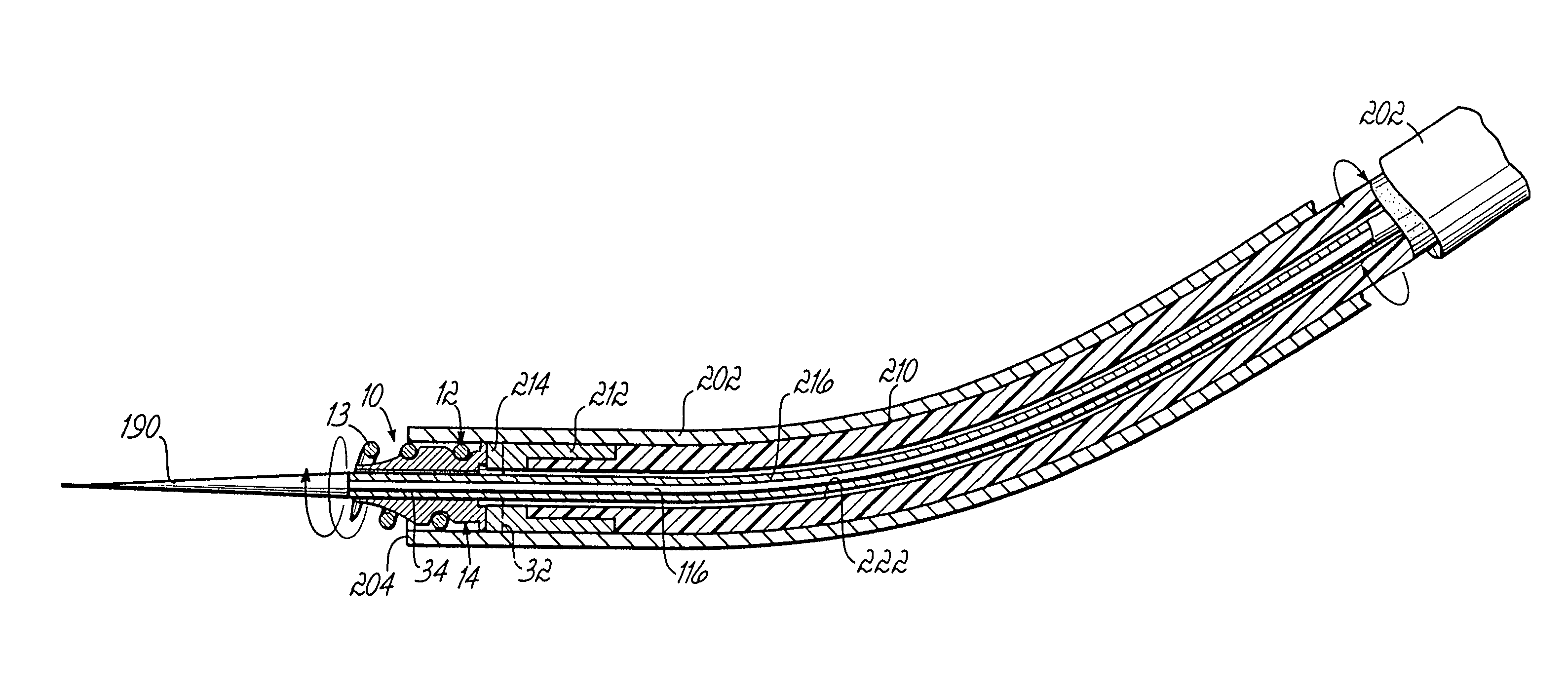
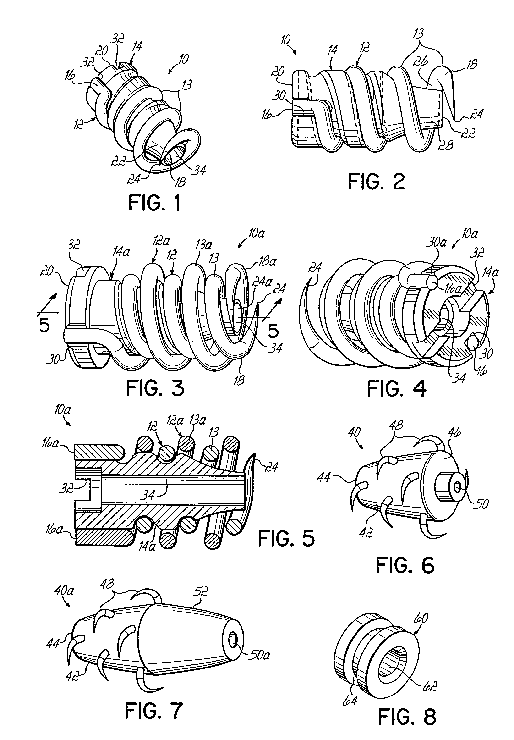
[0096]Referring now to FIGS. 1 and 2, an exemplary embodiment of the invention is described in connection with tendon-to-tendon or ligament-to-ligament repair. In this embodiment, a soft tissue anchor assembly 10 comprises a helical anchor 12 and a core portion or tendon fiber retaining member 14. Helical anchor 12 has proximal and distal ends 16, 18 and retaining member 14 likewise has proximal and distal ends 20, 22. The distal end 18 of helical anchor 12 extends distally beyond the distal end 22 of retaining member 14 and is sharpened to a point 24 to aid in insertion. In addition, retaining member 14 is tapered at its distal end 22 creating a space 26 between coils 13 of the helical anchor 12 and the outside surface 28 of the retaining member 14 for receiving and retaining tendon or ligament fibers therein, at least at a location near distal ends 18, 22 as will be discussed more fully below.

[0097]The proximal end 16 of helical anchor 12 is fixed to retaining member 14 at its pro...


PUM


Abstract

Apparatus and methods for repairing damaged tendons or ligaments. Various repair apparatus include an elongate tensile member and a pair of anchor assemblies connected for movement along the tensile member on either side of a repair site, such as a tear or laceration. The anchor assemblies or structures may take many forms, and may include barbed, helical, and crimp-type anchors. In the preferred embodiments, at least one anchor structure is movable along the elongate tensile member to assist with adjusting a tendon segment to an appropriate repair position and the anchor structure or structures are then lockable onto the elongate tensile member to assist with affixing the tendon at the repair position. Tendon and/or ligament-to-bone repair apparatus and methods employ similar concepts.

Description

[0001]The present application is a continuation of PCT Serial No. PCT / US02 / 31481 filed on Oct. 2, 2002, now pending, which is a continuation-in-part of U.S. application Ser. No. 09 / 969,947, filed on Oct. 3, 2001, now U.S. Pat. No. 6,984,241, which is a continuation-in-part of PCT Serial No. PCT / US99 / 24098 filed on Oct. 18, 1999, now expired, which is a continuation-in-part of U.S. Ser. No. 08 / 928,866, filed on Sep. 12, 1997, now U.S. Pat. No. 6,083,244, which is based on provisional patent application Ser. No. 60 / 026,101, filed Sep. 13, 1996, now abandoned, and provisional patent application Ser. No. 60 / 043,086, filed on Apr. 8, 1997, now abandoned. The disclosures of each of these prior related applications are hereby fully incorporated by reference herein.FIELD OF THE INVENTION[0002]The present invention generally relates to tendon or ligament repair apparatus and methods. More specifically, the invention relates to the repair of severed or otherwise damaged tendons or ligaments a...

Claims


Application Information

Patent Timeline
Patent Type & Authority Patents(United States)
IPC IPC(8): A61B17/58B25B23/00A61B17/04A61B17/06A61B17/064A61B17/08A61B17/11
CPCA61B17/0401A61B17/1146A61B17/1684A61B17/683A61B17/685A61F2/0811A61B17/0487A61F2002/0888A61B17/064A61B2017/0404A61B2017/0406A61B2017/0408A61B2017/0409A61B2017/0412A61B2017/0414A61B2017/0427A61B2017/0437A61B2017/044A61B2017/0441A61B2017/0445A61B2017/0454A61B2017/0456A61B2017/0458A61B2017/0461A61B2017/0462A61B2017/0464A61B2017/0488A61B2017/0496A61B2017/06028A61B2017/06057A61B2017/0641A61B2017/0646A61B2017/0648A61B2017/0649A61B2019/4805A61F2/0805A61F2002/0829A61F2002/0835A61F2002/0858A61B2090/0801
Inventor LUBBERS, LAWRENCE M.HUGHES, KENNETH E.COLEMAN, CARL R.WILLIAMSON, IV, WARREN P.BERKY, CRAIG B.WARD, THOMAS J.HUDDLESTON, MATTHEW J.GOLDIN, MARK A.CHRISTY, WILLIAM J.DEFAZIO, PERRYSCHUMACHER, BRIAN SCOTTMURPHY, TERENCE LEELEWIS, NICKOLA SYMONEJARRETT, JEREMYYOUNG, JOSEPH E.
Owner TENDON TECH
Why Eureka
Try Eureka