
Optical recording medium

a recording medium and optical technology, applied in the field of phase change optical recording media, can solve the problems of insufficient recording, inability to provide optical recording media capable of high-speed recording, and inability to meet the requirements of recording, etc., and achieve excellent archival stability and high compatibility

Inactive Publication Date: 2009-11-03
RICOH KK
View PDF36 Cites 0 Cited by
  • Summary
  • Abstract
  • Description
  • Claims
  • Application Information

AI Technical Summary

Benefits of technology

The medium achieves satisfactory recording at both high and low linear velocities, ensuring downward compatibility and archival reliability, with improved recording sensitivity and reduced jitter over repeated cycles.

Problems solved by technology

However, this optical recording medium does not take high-velocity recording and good downward compatibility (compatibility in recording at low linear velocity) into consideration.
However, these techniques alone cannot provide optical recording media capable of high-velocity recording and having good downward compatibility as in the present invention.
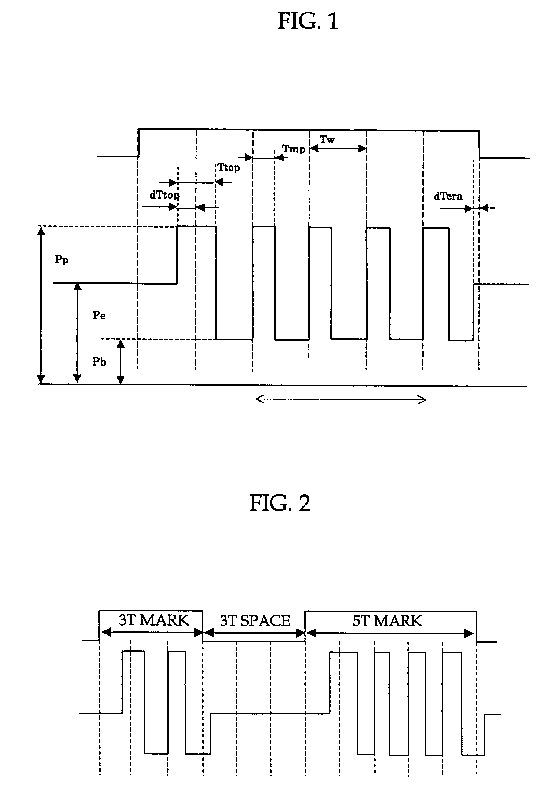
However, when the crystallization rate of the recording layer is increased, a record is not satisfactorily produced unless a higher recording power is used or a recording pulse wave pattern out of the multipulse of 1T period is used.
Accordingly, when a drive recordable at 1× to 2.4× speed with a maximum recording power of 15 mW is used on these media, records cannot be produced thereon due to insufficient power.
In addition, firmware alone cannot significantly change the recording pulse pattern.
If the recrystallization critical velocity is lower than the recording linear velocity, the phase-change material is not sufficiently crystallized in overwriting, and the produced records are not sufficiently erased.
When the recrystallization critical velocity is increased, the resulting medium will have markedly deteriorated archival stability and reliability.
At some set recrystallization critical velocities, these elements may not be added in sufficient amounts to improve the archival stability and reliability.
However, these configurations invite an increased recording power necessary to raise the phase-change material to a temperature at which the phase change occurs, and the resulting medium may not have satisfactory downward compatibility due to insufficient power.
However, these techniques do not teach improvement in overwriting properties, in particular at DOW1, and improvement in recording linear velocity and recording sensitivity.

Method used


Image

  • Optical recording medium
  • Optical recording medium
  • Optical recording medium

Examples


example a-1

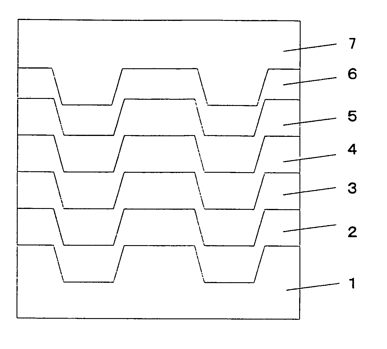
[0174]A disc having a lower protective layer, a recording layer, an upper interfacial layer, an upper protective layer, a sulfuration-inhibiting layer, and a reflective layer arranged on the substrate in this order was used. The lower protective layer comprised 80 mol % of ZnS and 20 mol % of SiO2 and had a thickness of 65 nm. The recording layer had a composition of Ag0.7In2.6Sb71.5Te20.9Ge4.3 and had a thickness of 15 nm. The upper interfacial layer was arranged between the recording layer and the upper protective layer, comprised 80 mol % of (ZrO2-3 mol % Y2O3) and 20 mol % of TiO2 and had a thickness of 2 nm. The upper protective layer comprised 80 mol % of ZnS and 20 mol % of SiO2 and had a thickness of 10 nm. The sulfuration-inhibiting layer comprised Si and had a thickness of 4 nm. The reflective layer comprised Ag and had a thickness of 140 nm.

[0175]The disc was initialized at a power of 1200 mW, a linear velocity of 9 m / s and a feed speed of 20 μm / r.

[0176]In this procedure,...

example a-2

[0182]A disc having a lower protective layer, a lower interfacial layer, a recording layer, an upper protective layer, a sulfuration-inhibiting layer, and a reflective layer arranged on the substrate in this order was used. The lower protective layer comprised 80 mol % of ZnS and 20 mol % of SiO2 and had a thickness of 63 nm. The lower interfacial layer was arranged between the recording layer and the lower protective layer, comprised 80 mol % of (ZrO2-3 mol % Y2O3) and 20 mol % of TiO2 and had a thickness of 2 nm. The recording layer had a composition of Ag0.7In2.6Sb71.5Te20.9Ge4.3 and had a thickness of 15 nm. The upper protective layer comprised 80 mol % of ZnS and 20 mol % of SiO2 and had a thickness of 12 nm. The sulfuration-inhibiting layer comprised Si and had a thickness of 4 nm. The reflective layer comprised Ag and had a thickness of 140 nm.

[0183]The disc was initialized at a power of 1200 mW, a linear velocity of 9 m / s and a feed speed of 20 μm / r.

[0184]In this procedure, ...

example a-3

[0187]A disc having a lower protective layer, a lower interfacial layer, a recording layer, an upper interfacial layer, an upper protective layer, a sulfuration-inhibiting layer, and a reflective layer arranged on the substrate in this order was used. The lower protective layer comprised 80 mol % of ZnS and 20 mol % of SiO2 and had a thickness of 63 nm. The lower interfacial layer was arranged between the recording layer and the lower protective layer, comprised 80 mol % of (ZrO2-3 mol % Y2O3) and 20 mol % of TiO2 and had a thickness of 2 nm. The recording layer had a composition of Ag0.7In2.6Sb71.5Te20.9Ge4.3 and had a thickness of 15 nm. The upper interfacial layer was arranged between the recording layer and the upper protective layer, comprised 80 mol % of (ZrO2-3 mol % Y2O3) and 20 mol % of TiO2 and had a thickness of 2 nm. The upper protective layer comprised 80 mol % of ZnS and 20 mol % of SiO2 and had a thickness of 10 nm. The sulfuration-inhibiting layer comprised Si and ha...


PUM

PropertyMeasurementUnit
dimensionsaaaaaaaaaa
groove widthaaaaaaaaaa

Abstract

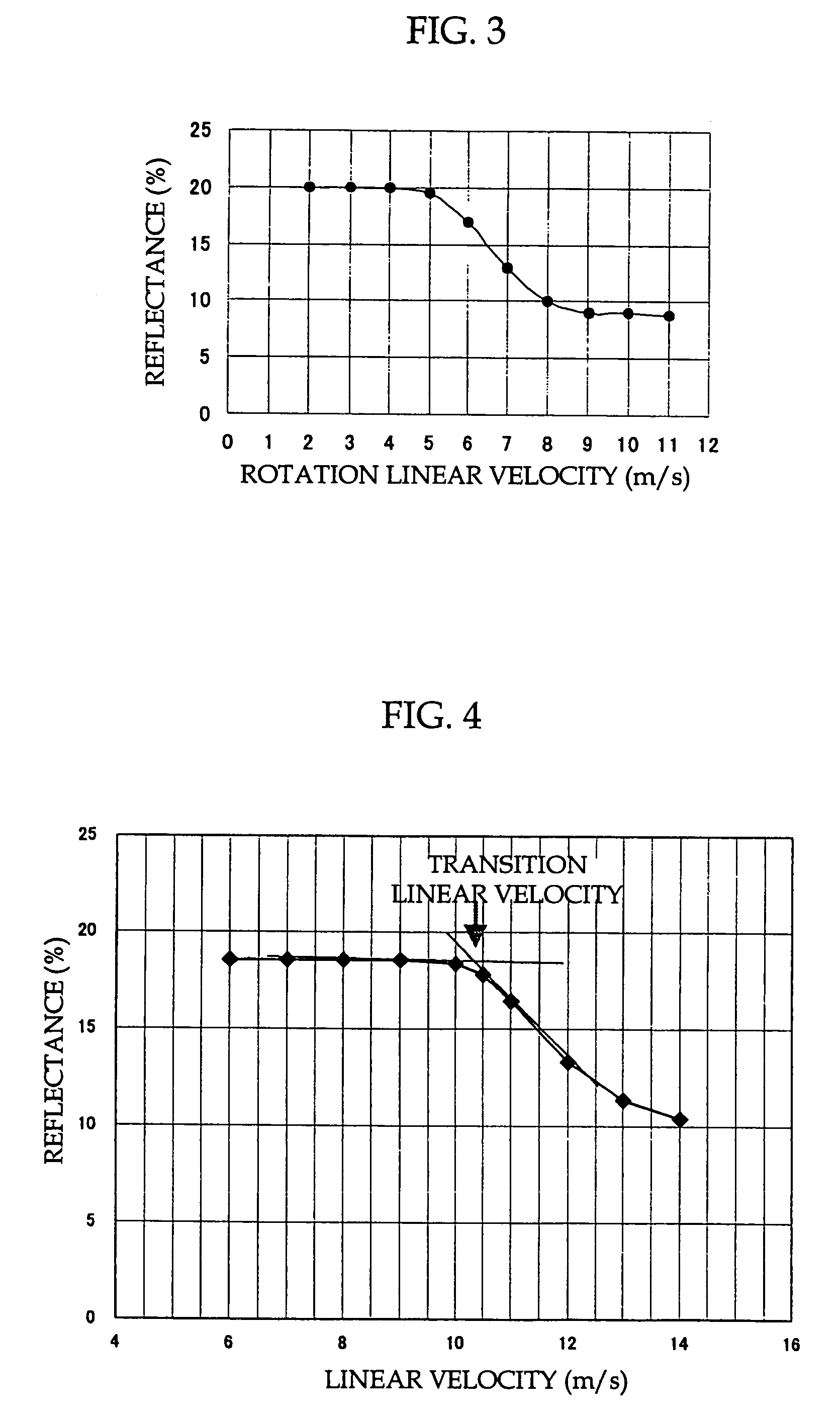
An optical disc having a transition linear velocity of 8-11 m / s when irradiating continuous light with 11±1 mW and a wavelength of 660±10 nm using a pickup head with a numerical aperture (NA) of 0.65, and satisfying the following condition:ΔR=|Rb−Ra|≦3%where Rb is a reflectance of an unrecorded area, and Ra is a reflectance of the top of an eye pattern after ten cycles of recording. In one recording mode therefor, the disc is rotated at a constant angular velocity so as to have a linear velocity of 3-4 m / s on an innermost track and a linear velocity of 8-9 m / s on an outermost track. In another mode, the disc is rotated at a constant angular velocity so as to have a linear velocity of 5-6 m / s on an innermost track and a linear velocity of 13-14 m / s on an outermost track.

Description

[0001]This is a continuation application of U.S. patent application Ser. No. 10 / 660,564, filed on Sep. 12, 2003, the entire disclosure of which is incorporated by reference herein.BACKGROUND OF THE INVENTION[0002]1. Field of the Invention[0003]The present invention relates to phase-change optical recording media recordable and reproducible over a broad range of linear velocities.[0004]2. Description of the Related Art[0005]An example of phase-change optical recording media having high compatibility in reproduction by DVD-ROM drives can be found in Japanese Patent Application Laid-Open (JP-A) No. 2002-237096. However, this optical recording medium does not take high-velocity recording and good downward compatibility (compatibility in recording at low linear velocity) into consideration.[0006]Examples of means for achieving satisfactory recording at high velocity can be found in Japanese Patent (JP-B) No. 3150267, JP-A Nos. 2001-56958 and 2002-96560, in which the composition of a reco...

Claims


Application Information

Patent Timeline
Patent Type & Authority Patents(United States)
IPC IPC(8): B32B3/02G11B7/24G11B7/243G11B7/253G11B7/2534G11B7/257G11B7/259
CPCG11B7/0062G11B7/24G11B7/243G11B7/252G11B7/257G11B7/259Y10T428/21G11B2007/24314G11B2007/24316G11B7/2534
Inventor DEGUCHI, HIROSHIYUZURIHARA, HAJIMEHIBINO, EIKOMIURA, HIROSHIABE, MIKIKONARUMI, SHINYAKIBE, TAKESHIYAMADA, KATSUYUKITANIGUCHI, SATOSHI
Owner RICOH KK
Learn More