Method and apparatus for monitoring energy storage devices

a technology for energy storage devices and monitoring methods, applied in emergency power supply arrangements, powerline communications applications, instruments, etc., can solve the problems of increasing the cost of batteries and overall ups system, and increasing the monitoring capacity. , the effect of cost-effectiveness

Active Publication Date: 2009-11-03
AMERICA POWER CONVERSION CORP
View PDF102 Cites 26 Cited by
  • Summary
  • Abstract
  • Description
  • Claims
  • Application Information

AI Technical Summary

Benefits of technology

[0007]Monitor circuits that are a part of the battery module are either traditionally very simple, and do not provide adequate monitoring capability or are very complex and also prove to be another point of failure in the system. For example, in one such system, only the current temperature output voltage and current indications are provided under certain conditions. For example, temperature readings are provided only when a switch is operated in a sensor of the battery module and is monitored by the UPS system. Also, more complex monitoring circuits inside the battery include many parts that are subject to failure, and increase the cost of the batteries and overall UPS system. Conventional monitoring circuits that are installed in a battery use battery power when running and when in storage. It would be beneficial to have a battery monitoring circuit that does not drain batteries when in storage or during normal operating period of the UPS system.
[0008]There is also a need for an inexpensive battery monitor circuit. However, a monitor is desired that provides increased monitoring capabilities. It is a challenge to provide a cos...

Problems solved by technology

There are many disadvantages of current battery monitoring technologies currently used in UPS systems.
In particular, dedicated monitor circuits allocated to each battery are generally expensive and include complex circuits that serve as another point of failure in the UPS system.
Because data is not retained with the battery, it is more difficult to troubleshoot problems with failed batteries.
Further, inadequate battery modules may then be erroneously installed in the problem UPS or other UPS syst...

Method used


Image

  • Method and apparatus for monitoring energy storage devices
  • Method and apparatus for monitoring energy storage devices
  • Method and apparatus for monitoring energy storage devices

Examples


Embodiment Construction

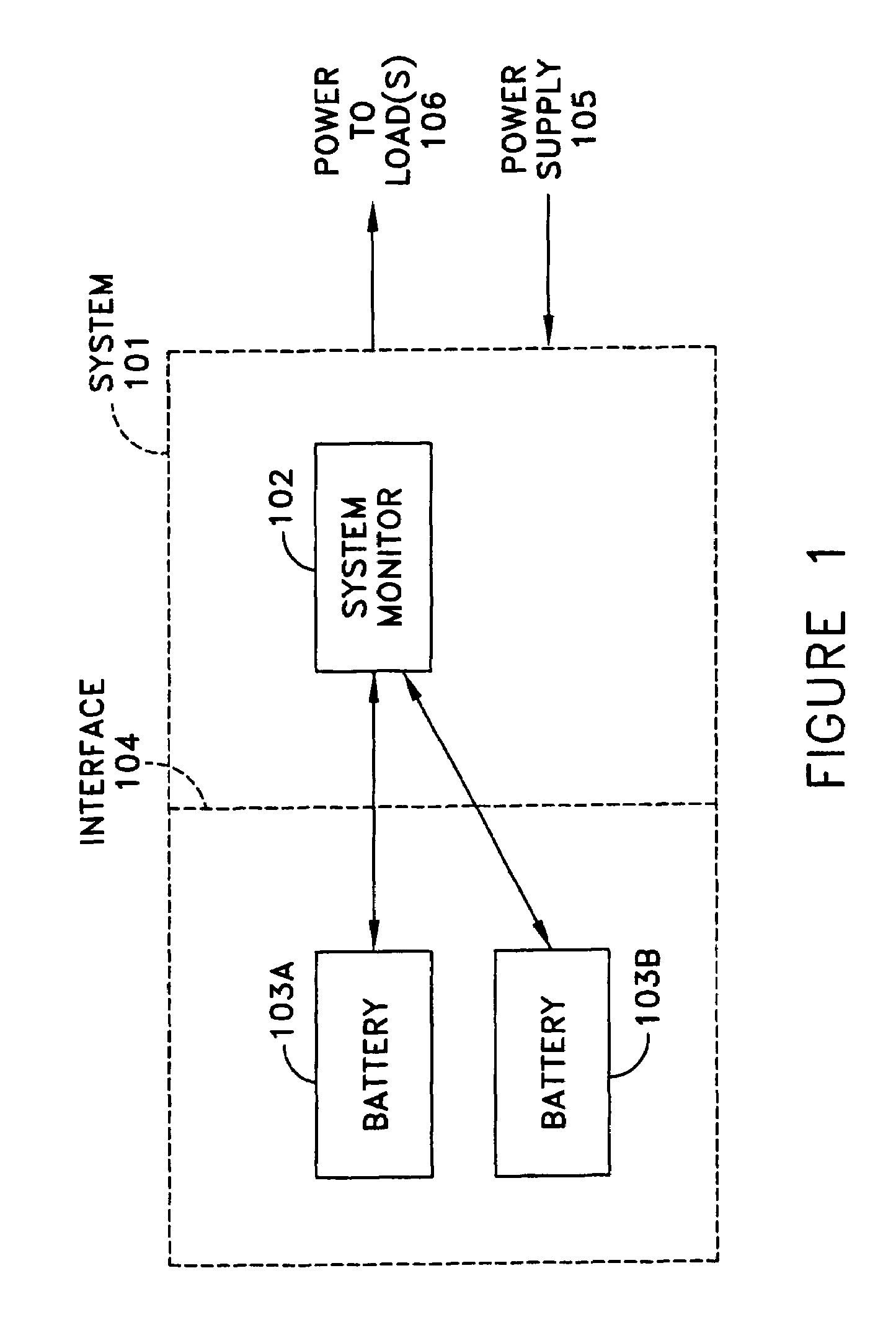
[0039]FIG. 1 shows a system 101 in which various embodiments of the invention may be practiced. For instance, system 101 may be a UPS system having a system monitor 102 and one or more batteries 103A-103B. System monitor 102 may perform monitoring of the overall UPS system 101, and may monitor the one or more batteries 103A-103B through a communication interface 104. Interface 104 may be any interface used to communicate data, however, various aspects of the invention as described in more detail below describe an improved battery monitor and associated communications interface for use in communication with a battery or other energy storage device of a UPS.

[0040]UPS system 101 may be, for example, an AC-AC or AC-DC class UPS system. UPS systems and their circuitry are well-known in the art, and are available commercially from a number of companies including the American Power Conversion Corporation located in West Kingston, RI. System 101 may also include circuitry that, when system1...


PUM


Abstract

An improved battery, monitoring circuit and method for communicating with the battery is provided. Such batteries and communication methods are particularly useful in UPS systems that use such batteries to provide back-up power to electrical loads. In one aspect, performance, manufacturing, trend and/or other data are stored in non-volatile memory of the battery and are communicated to an external system such as a UPS. In another aspect, a method for communicating via single-wire interface is provided. In one aspect, a same interface is used to communicate with both conventional batteries and improved batteries having increased monitoring capabilities.

Description

FIELD OF THE INVENTION[0001]The field of the invention relates generally to energy storage devices, and more particularly, to energy storage devices used in an Uninterruptible Power Supply (UPS) system.BACKGROUND[0002]There are numerous types of Uninterruptible Power Supply (UPS) systems for supplying backup alternating current (AC) or direct current (DC) power to electrical loads. These UPS systems generally use batteries or types of other energy storage devices that supply such power when a main power supply (e.g., line power) is not available. For example, backup power is provided when power from an AC source performs outside acceptable limits or fails altogether.[0003]These UPS systems generally use multiple energy storage devices configured in parallel or in series to provide backup power. In such systems, it is important to be able to accurately estimate the remaining time period that the UPS system can supply backup power. Conventionally, UPS systems connected to energy stora...

Claims


Application Information

Patent Timeline
IPC IPC(8): H02J7/00G01R31/36H04B3/54
CPCH01M10/48H02J7/0021H04B2203/547H04B2203/5458H04B2203/5412Y02E60/10H02J7/0013H02J7/005H02J7/0047
Inventor MUTABDZIJA, SRDANDEMISSIE, EYOBMASCIARELLI, FRANCIS J.FALCINELLI, MICHAEL
Owner AMERICA POWER CONVERSION CORP
Why Eureka
Try Eureka