Supercharge Your Innovation With Domain-Expert AI Agents!

Apparatus and method of driving light source for image display device and image display device having the same

a technology of image display device and light source, which is applied in the field of system for displaying images, can solve problems such as noise in signals from magnetic fields generated by lamps

Inactive Publication Date: 2009-11-03
SAMSUNG DISPLAY CO LTD
View PDF9 Cites 5 Cited by
  • Summary
  • Abstract
  • Description
  • Claims
  • Application Information

AI Technical Summary

Benefits of technology

The present invention provides a device and method for driving a light source for image display devices. The device includes a signal controller that generates a synchronization signal and an inverter that generates a driving signal synchronized with the synchronization signal. The driving signal includes a wave signal that has a rising slope interval and a falling slope interval that are substantially equal to each other during a gate-on voltage interval in which data voltage is charged in corresponding pixels. The synchronization signal has a phase difference of 90° with respect to the gate control signal. The method includes providing a gate signal to control activation of pixels, providing a data voltage to activated pixels to display images, generating a gate control signal to control timing of the gate-on voltage, phase-shifting the gate control signal to generate the synchronization signal, and generating a driving signal to drive the light source. The driving signal has a sinusoidal wave that is substantially symmetric with respect to a vertical center line during the gate-on voltage interval. The technical effects of the invention include improved image display quality and reduced power consumption.

Problems solved by technology

Since the lamps in an LCD device are closely disposed at the rear side of an LCD panel at a distance of several millimeters, electric and / or magnetic fields generated from the lamps make noise to signals in wires and thin film transistors (TFTs) of the LCD panel.
In particular, since the frequency of a driving signal for the lamps and the frequency of a horizontal synchronization signal for the LCD panel are similar but slightly different from each other, a beating occurs to cause interference that makes horizontal stripes, called “waterfall,” on a screen of the LCD device.

Method used


Image

  • Apparatus and method of driving light source for image display device and image display device having the same
  • Apparatus and method of driving light source for image display device and image display device having the same
  • Apparatus and method of driving light source for image display device and image display device having the same

Examples


Embodiment Construction

[0022]Detailed illustrative embodiments of the present invention are disclosed herein. However, specific structural and functional details disclosed herein are merely representative for purposes of describing exemplary embodiments of the present invention. In the drawings, the thickness and / or length of layers and regions may be exaggerated for clarity.

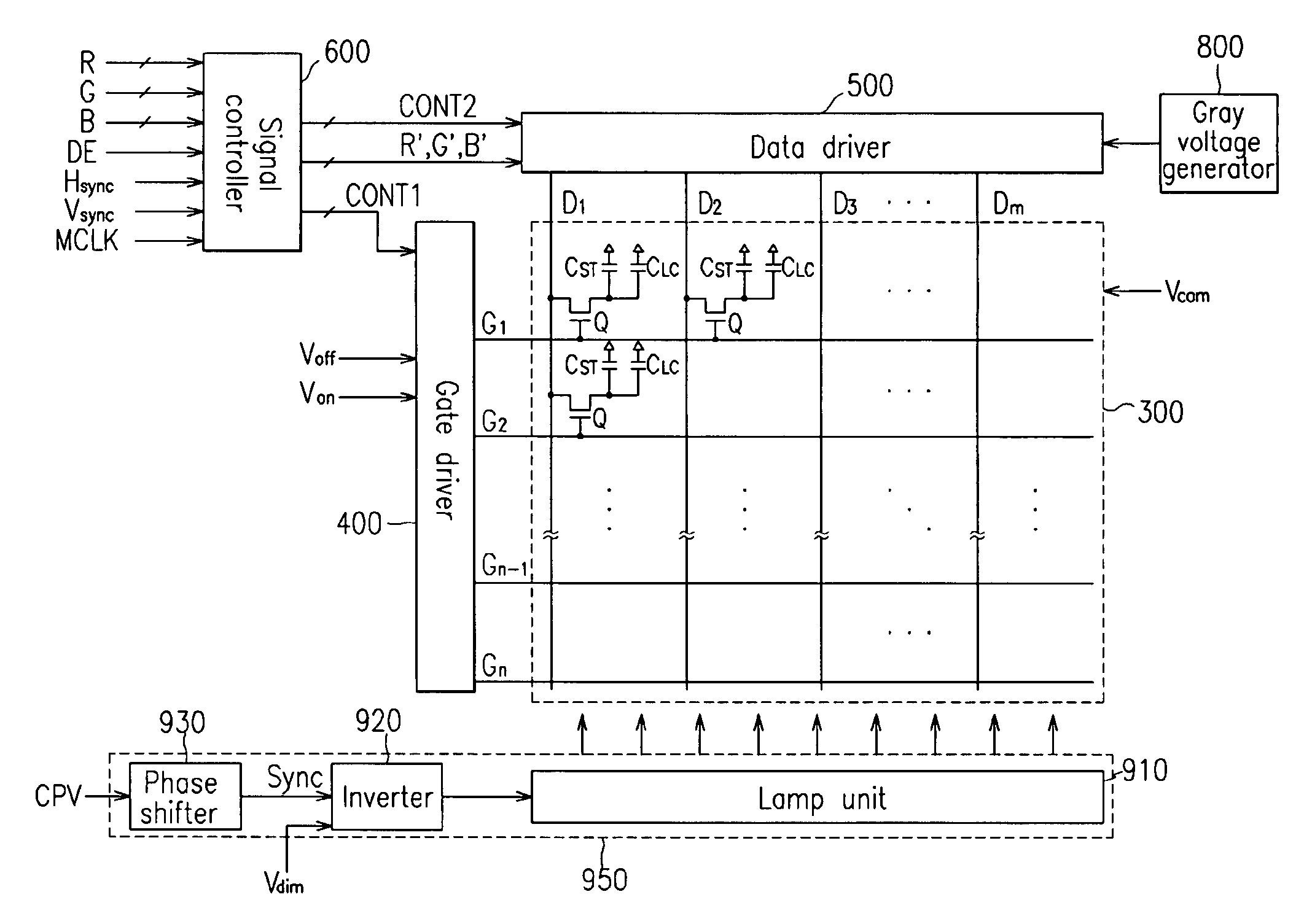
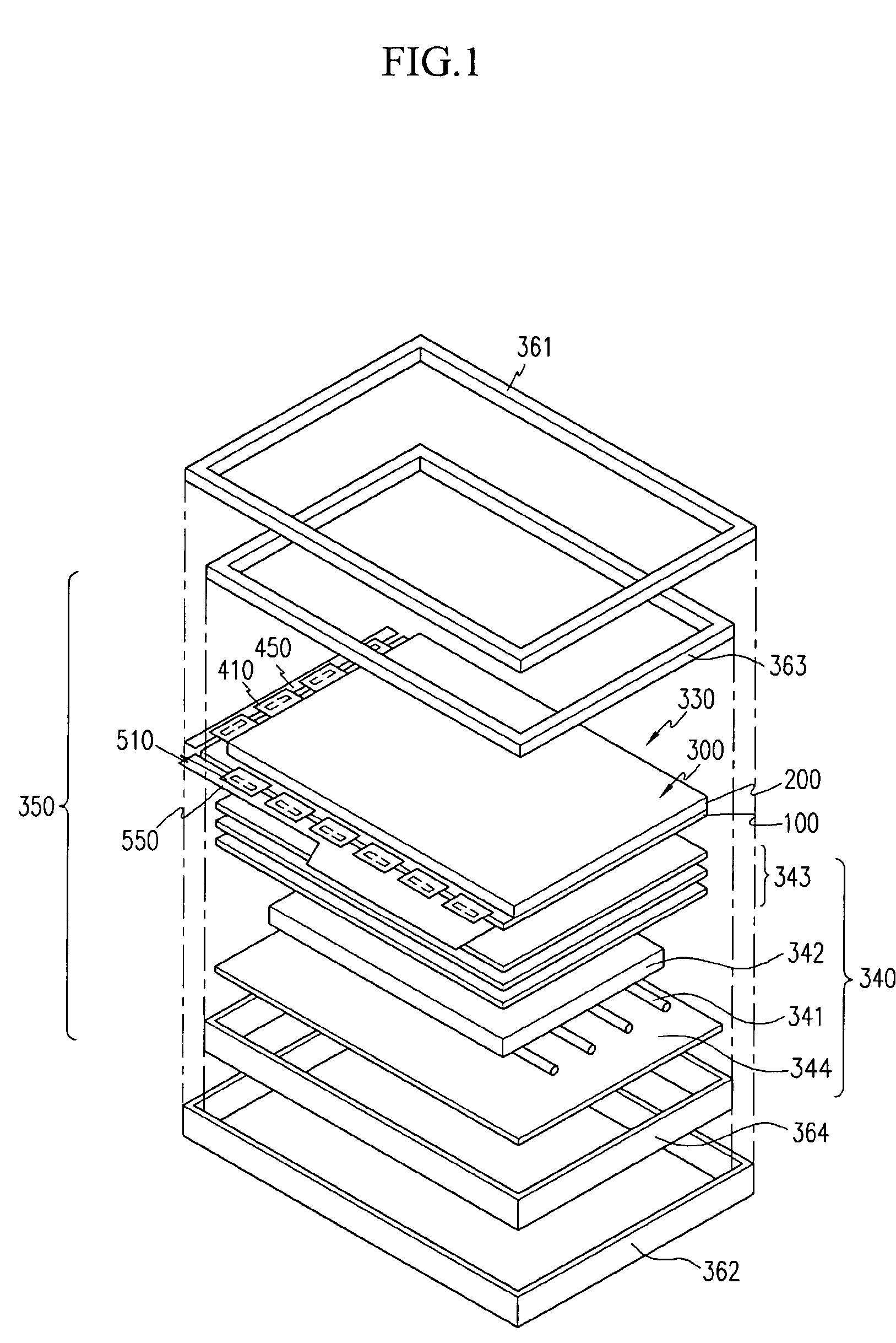
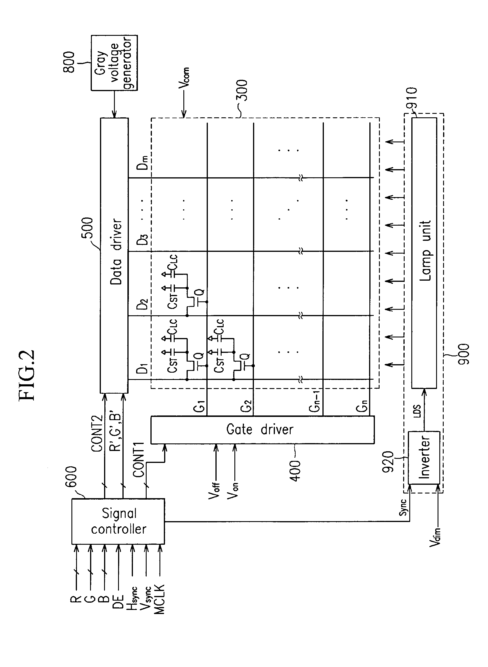
[0023]A liquid crystal display (LCD) device according to an embodiment of the present invention is described below with reference to FIGS. 1 to 3. FIG. 1 is an exploded perspective view of an LCD device according to an exemplary embodiment of the present invention, FIG. 2 is a block diagram of certain parts of the LCD device in FIG. 1, and FIG. 3 is an equivalent circuit diagram of a pixel of the LCD device in FIGS. 1 and 2.

[0024]Referring to FIG. 1, the LCD device includes a liquid crystal (LC) module 350, front and rear cases 361 and 362, a chassis 363 and a mold frame 364 that receive and stably contain the LC module 350. The LC mo...


PUM

PropertyMeasurementUnit
gate-on voltageaaaaaaaaaa
gate-off voltageaaaaaaaaaa
phaseaaaaaaaaaa

Abstract

An image display device includes a display panel having gate and data lines electrically connected with pixels, gate and data drivers providing a gate signal and a data voltage, respectively, to corresponding ones of the pixels, and an inverter providing a lamp driving signal to drive a lamp unit. The lamp driving signal includes a wave signal of which rising and falling slope intervals are substantially equal to each other during a gate-on voltage interval in which the data voltage is charged in corresponding one of the pixels. The image display device also includes a signal controller for generating a gate control signal to control timing of generation of the gate-on voltage and a synchronization signal having a 90° phase difference with respect to the gate control signal. The synchronization signal is provided to the inverter.

Description

BACKGROUND OF THE INVENTION[0001]1. Field of the Invention[0002]The present invention relates to a system for displaying images, and more particularly to, a device and a method of driving a light source for image display devices and an image display device having the same.[0003]2. Description of the Related Art[0004]Image display devices, such as computer monitors, television sets, etc., generally include self-emitting display devices and non- emitting display devices. The self-emitting display devices are ones that actively emit light themselves to display images, such as light emitting diode (LED) display devices, electroluminescence (EL) display devices, vacuum fluorescent display (VFD) devices, field emission display (FED) devices, and plasma panel display (PDP) devices. In contrast, the non-emitting display devices are ones that use light externally provided from a light source, such as liquid crystal display (LCD) devices.[0005]The LCD devices generally include two panels havi...

Claims


Application Information

Patent Timeline
Patent Type & Authority Patents(United States)
IPC IPC(8): G09G3/36G09G3/20G02F1/133G09G3/34
CPCG09G3/3406G09G3/3648G09G3/3677G09G3/2074G09G3/3614G09G2330/06G09G2310/024G09G2310/08G09G2320/02G09G2320/0204G09G3/3688G09G3/36
Inventor KIM, MIN-HONG
Owner SAMSUNG DISPLAY CO LTD
Features
  • R&D
  • Intellectual Property
  • Life Sciences
  • Materials
  • Tech Scout
  • Unparalleled Data Quality
  • Higher Quality Content
  • 60% Fewer Hallucinations
Learn More