Procedure and device for improving the maneuverability of an aircraft during the approach to landing and flare-out phases

Active Publication Date: 2009-11-10
AIRBUS OPERATIONS SAS
View PDF18 Cites 0 Cited by
  • Summary
  • Abstract
  • Description
  • Claims
  • Application Information

AI Technical Summary

Benefits of technology

[0027]The inventors have considered using this property in the event of an approach at a steep flight path angle. Thus, thanks to the deployment of the air brakes, the steep flight path angles imposed by airports in urban areas can be complied with by the airplanes.
[0028]The inventors have however observed that at the time of flare-out (when the pilot pulls back on the control stick (or wheel) to redress the aircraft before touchdown on the runway), the aircraft is in this configuration less maneuverable. In effect, the aircraft responds too slowly to the pilot's request compared to the case where the air brakes are retracted. This is due to the fact that in order to redress the aircraft and to break the flight path angle, it is necessary to generate a greater load factor and that the time attributed to this action is shorter than in a classic approach. In order to generate this load factor it is necessary to increase the incidence and hence the trim by a greater value than in a classic approach. To reduce the flight path angle down to a value which ensures a sufficiently soft impact, it is also necessary to proceed to a trim change of a greater value than in a classic approach, because the original flight path angle is greater. Thus, the trim engagements during the flare-out are almost two times greater during a steep angle approach than during a classic approach. The steeper the angle, the greater must be the trim variation. Thus the outside references of the pilot are completely modified and piloting in this flight phase, under these particular conditions, becomes less natural and makes demands on the pilot for an adaptation phase and heightened attention.
[0036]In other words, the retraction of the air brakes from the first position to the second position according to the invention allows achieving a flare-out which allows to maintain to a large extent the same angle of incidence, corresponding, in case of an approach at a steep flight path angle, to a flare-out with the usual exterior piloting references during the flare-out phase.
[0046]The present invention also concerns a device for improving the maneuverability of an aircraft during the approach to landing and then flare-out phases, with the aircraft being equipped with air brakes.

Problems solved by technology

The inventors have however observed that at the time of flare-out (when the pilot pulls back on the control stick (or wheel) to redress the aircraft before touchdown on the runway), the aircraft is in this configuration less maneuverable.

Method used


Image

  • Procedure and device for improving the maneuverability of an aircraft during the approach to landing and flare-out phases
  • Procedure and device for improving the maneuverability of an aircraft during the approach to landing and flare-out phases
  • Procedure and device for improving the maneuverability of an aircraft during the approach to landing and flare-out phases

Examples


Embodiment Construction

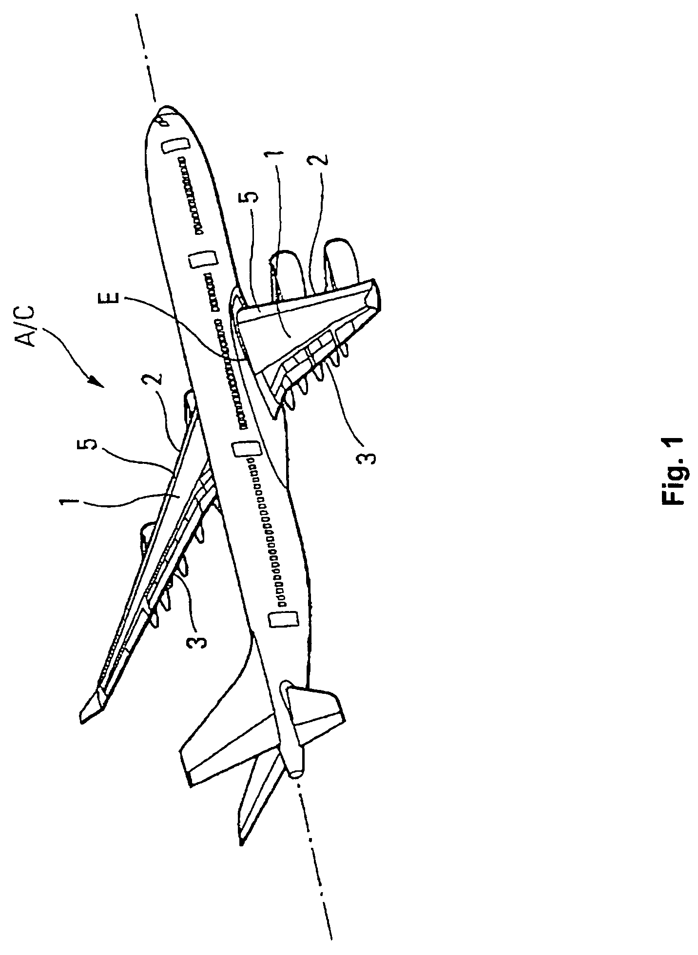
[0067]The A / C jumbo jet shown in FIG. 1 has two wings 1.

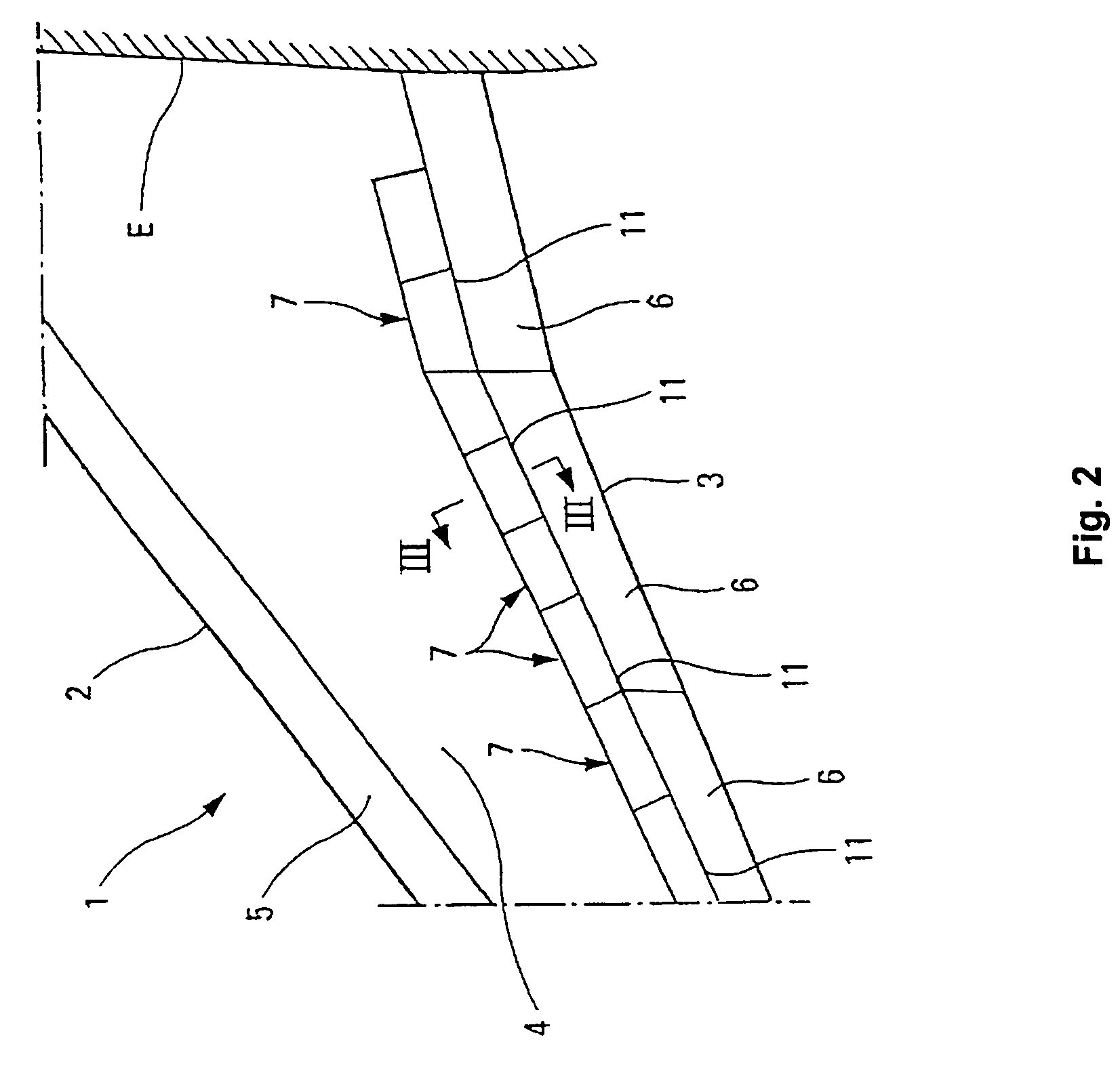
[0068]As shown at a larger scale in FIG. 2, each wing 1 includes a leading edge 2, a trailing edge 3, a wing top 4 and a wing root E.

[0069]The leading edge 2 is formed by at least one high lift leading edge slat 5.

[0070]The trailing edge 3 of wing 1 is formed by the juxtaposition of the trailing edges of a number of adjacent trailing edge flaps 6.

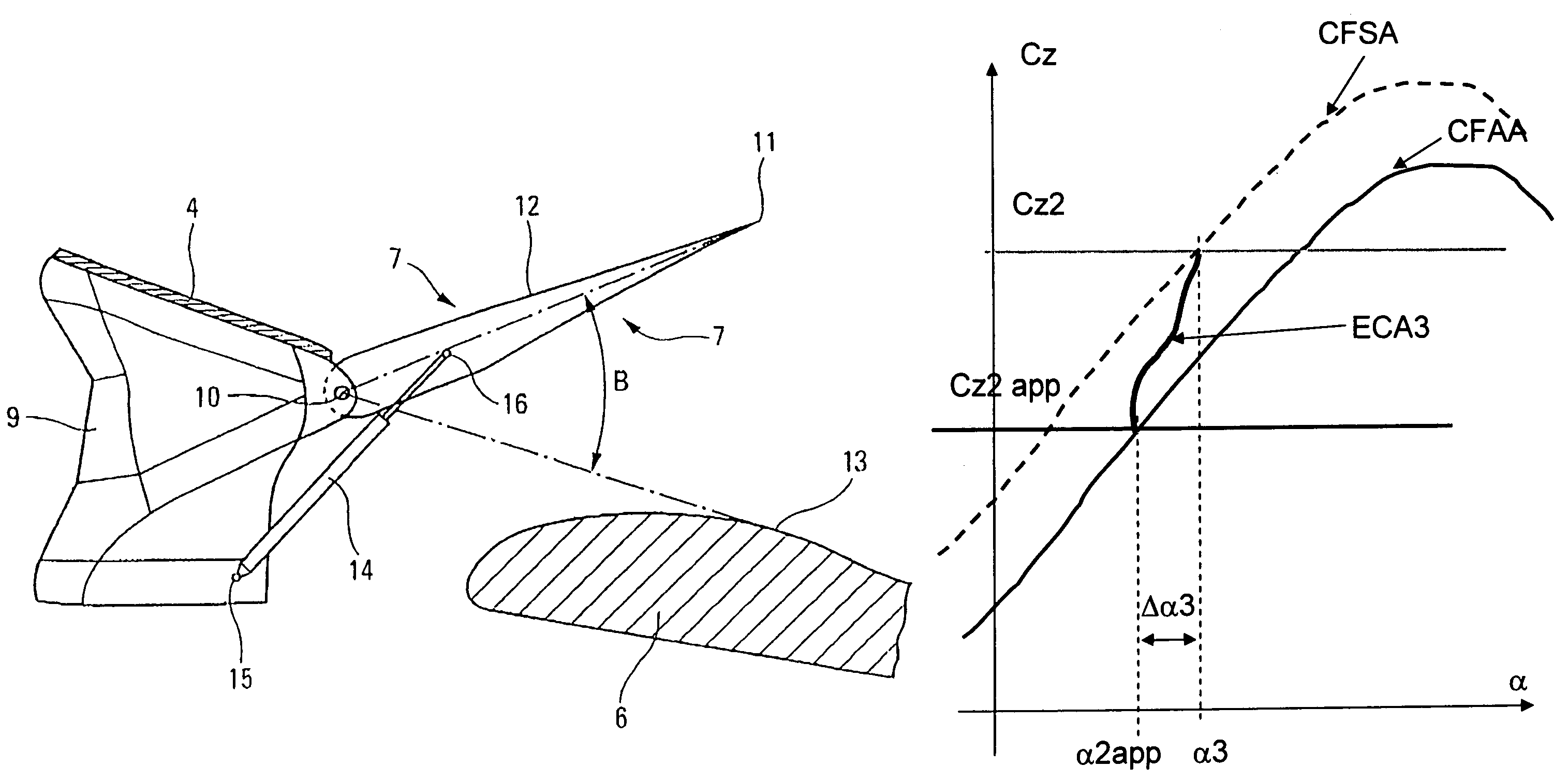
[0071]In the top side 4 of the wing, upstream of the trailing edge flaps 6 (with respect to the aerodynamic flow over the wing 1), is located a number of deflecting flaps 7, whose plane form is that of a rectangle or of a rectangular trapezoid.

[0072]As is shown in FIG. 3, each deflecting flap 7 is hinged, on the side of its leading edge 8, to the structure 9 of wing 1 around an axis 10, parallel to the leading edge 8.

[0073]In the retracted position represented in FIGS. 2 and 3, the trailing edge 11 of each deflecting flap 7 is supported by a trailing edge flap 6 and the top side 12 of ...


PUM


Abstract

The process improves the maneuverability of an aircraft during the approach to landing and then flare-out phases, the aircraft being equipped with air brakes. According to the process, the air brakes are put in a first deployed position during the approach phase, and as a function of a representative parameter of a given altitude and in case of a steep angle approach, they are actuated to transition to a second more retracted position than the first position so as to achieve a flare-out allowing to essentially maintain the same angle of incidence, corresponding in case of a steep angle approach to achieve a flare-out with habitual exterior piloting references during the flare-out phase.

Description

BACKGROUND OF THE INVENTION[0001]1. Field of the Invention[0002]This invention concerns the improvement of the maneuverability of an aircraft during the approach to landing and then flare-out phases with the aid of an appropriate control of the spoiler flaps, also called air brakes.[0003]2. Discussion of the Background[0004]By “improving the maneuverability of an aircraft” one understands here that which facilitates its operation.[0005]The main portion of approaches to landing, with respect to commercial aircraft is carried out under a classic flight path angle γ of −3° approximately.[0006]In reference to FIG. 5, please note that the flight path angle γ corresponds to the angle between the velocity vector V of the center of gravity C of the aircraft and the horizon H.[0007]The trim θ is the angle between the axis A of the aeroplane A and the horizon H, and the angle of incidence α the angle between the axis A of the aircraft and the velocity vector V. The relationship connecting the...

Claims


Application Information

Patent Timeline
IPC IPC(8): B64C9/32
CPCB64C9/20B64C9/32B64C19/02G05D1/0676B64C13/16Y02T50/32Y02T50/30
Inventor BOISSENIN, STEPHANEROSAY, JACQUES
Owner AIRBUS OPERATIONS SAS
Why Eureka
Try Eureka