Medical pump device

a pump device and pump technology, applied in the direction of multiple way valves, flow control, instruments, etc., can solve the problems of inability to precisely determine the position of the piston and the ejection volume, affecting the application of high concentration, and affecting the effect of high concentration

Inactive Publication Date: 2009-11-10
MEDINNOVATION
View PDF18 Cites 40 Cited by
  • Summary
  • Abstract
  • Description
  • Claims
  • Application Information

AI Technical Summary

Benefits of technology

[0015]By the rotary valve with preferably uniformly distributed connections and pump chamber a very simple design is arrived at. The preferably single rectilinear channel allows a safe rinsing of the device and avoids projections on which air bubbles can grow.
[0019]The proposed principle allows specifically to reduce to a large extent volume effects which are caused by changes of the hydrostatic pressure, because the feed of the liquid is no longer set basically by the applied pressure to a larger volume, but rather by the number of drainages of the volumina V.
[0021]The device for a volume controlled pumping of a liquid medium in the field of medical applications allows, thus, the controlling of the mass flow by a discretising of the drainable liquid volume by use of cyclically fillable and drainable volumina with a precisely defined content. The position of the device is somewhere in the conduit between reservoir and patient. Preferred is a bypass function for the venting of the system. Preferred is the separation of the device into once usable chamber components and multiply usable components (driver, control). Preferably control elements (e.g. air detectors, pressure sensors) are employed for the monitoring of the proper function of the device. The reservoir is realized by infusion bag, bottle or preferably by a syringe driver or a pressurized infusion syringe, respectively. By the pump device according to the invention the demand made on accuracy of the reservoir or the reservoir draining mechanism, respectively which serves now merely for the filling of the pump device is, thereby, considerably lowered.

Problems solved by technology

Overly large fluctuations of the mass flow could be perilous in case of use of highly concentrated potent, short-time active medicaments.
Elastic deformations and momentary jamming (sticking-effect) lead to the situation that no precise relation between position of the piston and ejected volume exists.
Infusion pumps, at the other hand, such as known e.g. by the U.S. Pat. No. 6,213,723 are as a rule less suitable for the application of highly concentrated, short-time active medicaments at low mass flows.
Both infusion systems have the drawback that they provide no control over the actual precisely dispensed amount of liquid [13-16].
Because, however, at this pump up to 75% of the resilient membrane surface is exposed and not acted upon by the associated piston, there results also a considerable dependency of this cassette pump from the inlet pressure of the liquid and, thus, the height position of the infusion container.

Method used


Image

  • Medical pump device
  • Medical pump device
  • Medical pump device

Examples


Embodiment Construction

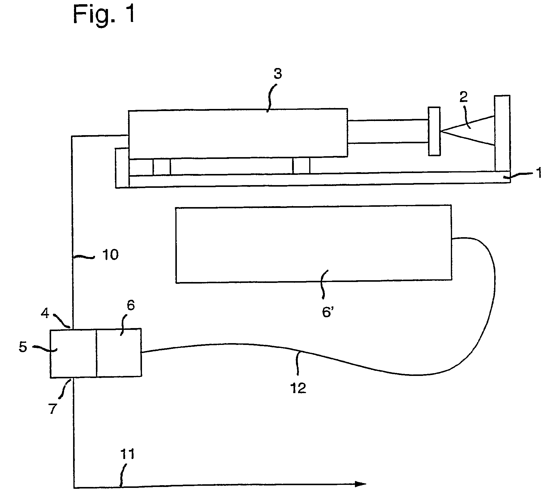
[0041]FIG. 1 illustrates rough schematically the preferred use of the medical pump device or the pump system, respectively. It includes at the one hand a as such known infusion syringe driver with a infusion syringe slide 1 which can receive a infusion syringe 3 which is operated by a syringe driver 2 (in the simplest case a spring), so that a ejecting of the liquid in the infusion syringe 3 occurs with a predetermined amount per time unit (motor) or a relatively constant pressure (spring). Corresponding infusion syringe drivers are known and are not explained herein in detail. According to the prior art the outlet of the syringe pump 1 is directly coupled to the patient, or supplies a catheter, respectively. According to the invention a pump system is now provided in which the infusion syringe 3 serves merely for supplying the pump device 4-7 through the conduit 10. The conduit 10 runs, thereby, from the outlet of the syringe pump 1 to a inlet connector 4 of the pump device 4-7. A ...


PUM


Abstract

The invention relates to a medical pump device comprising a rotary valve (13) having preferably only one rectilinear channel (20) which respectively connects the inlet (4) and the outlet (7) of the pump device, or connects the inlet to a pump chamber (15), or said pump chamber to the outlet, upon rotation of the rotary element (19) of the valve. The invention enables a medical pump device to be especially easily produced, said pump device being preferably inserted between an infusion syringe driver or an infusion container and a catheter, and being used to supply small quantities of liquid in an accurately dosed manner.

Description

REFERENCE TO RELATED APPLICATIONS[0001]This application is a 371 national phase of PCT / IB02 / 04771 filed on 15 Nov. 2002, the content of which is incorporated herein by reference in its entirety.[0002]This application claims the priority of the Swiss patent application No. 2110 / 01 of Nov. 16, 2001 and the Swiss patent application No. 857 / 02 of May 27, 2002, of which the contents shall be considered incorporated in the disclosure of the present application by reference thereto.TECHNICAL FIELD[0003]The invention relates to a medical pump device according to the introductory portions of the claims 1, 2 and 11. The invention relates further to a pump system according to claim 12.PRIOR ART[0004]For a continuous application of liquids or medicines infusion pumps and injection pumps are used. Whereas liquids are fed at infusion pumps by means of a squeegee acting onto a hose, the medical solution is ejected at the injection pump by a displacing of the piston of the syringe. At the latter sy...

Claims


Application Information

Patent Timeline
Patent Type & Authority Patents(United States)
IPC IPC(8): F04B7/00A61M5/168A61M5/14A61M5/142A61M5/145A61M39/22
CPCA61M39/223A61M5/14A61M5/142A61M5/14216A61M2005/14264A61M2005/1402A61M5/1456Y10T137/86871
Inventor FUECHSLIN, RUDOLF MARCELWEISS, MARKUSDUENKL, RUDOLFMEJER, PETER FRITZNEFF, THOMASSTOLL, ERICH PAULSUTER, ANDREAS
Owner MEDINNOVATION
Why Eureka
Try Eureka