Three phase inverter with improved loss distribution

a three-phase inverter and loss distribution technology, applied in the direction of electric variable regulation, process and machine control, instruments, etc., can solve the problems of limited in the ability of the inverter to increase the available power and/or decrease the current rating, and reduce the motor torque at low speeds

Inactive Publication Date: 2009-11-10
GM GLOBAL TECH OPERATIONS LLC
View PDF13 Cites 32 Cited by
  • Summary
  • Abstract
  • Description
  • Claims
  • Application Information

AI Technical Summary

Problems solved by technology

Even this arrangement, however, can be limited in its ability to increase available power and / or to decrease the current rating of the inverter.
In particular, thermal constraints at low fundamental operating frequencies can make it difficult for conventional inverter circuits to produce desired levels of current, thereby resulting in decreased motor torque at low speeds.

Method used


Image

  • Three phase inverter with improved loss distribution
  • Three phase inverter with improved loss distribution
  • Three phase inverter with improved loss distribution

Examples


Embodiment Construction

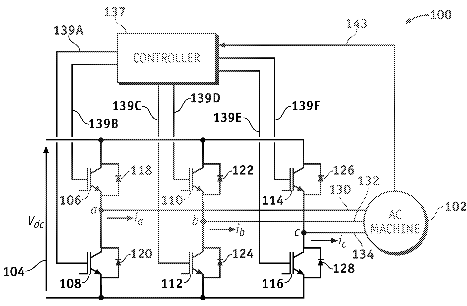
[0012]The following description generally relates to methods and systems for storing and boosting the electrical power available in a multi-motor electrical system such as that found on many hybrid automobiles, trucks and other vehicles. Equivalent concepts, however, may be readily applied in other vehicular, industrial, aerospace and / or other settings. Indeed, the various concepts described herein may be readily adapted to any modulated inverter system whatsoever. In this regard, the following detailed description is merely exemplary in nature and is not intended to limit the invention or the application and uses of the invention. Furthermore, there is no intention to be bound by any expressed or implied theory presented in the preceding technical field, background, brief summary or the following detailed description.

[0013]The following description refers to elements or nodes or features being “connected” or “coupled” together. As used herein, unless expressly stated otherwise, “co...


PUM


Abstract

An inverter circuit couples a DC voltage source having a primary side and a reference side to an electric motor or other AC machine having multiple electrical phases. An inverter circuit includes switches, diodes and a controller. For each of the electrical phases, a first switch couples the electrical phase to the primary side of the DC voltage source and a second switch couples the electrical phase with the reference side of the DC voltage source. For each of the first and second switches, an associated anti-parallel diode is configured to provide an electrical path when the switch associated with the diode is inactive. The controller is coupled to the switching inputs of each of the first and second switches and is configured to provide a control signal thereto, wherein the control signal provided to each switch comprises, in a low frequency mode, a first portion and a second portion, wherein the first portion comprises a first pulse width modulation scheme and the second portion comprises a second pulse width modulation scheme different from the first modulation scheme.

Description

TECHNICAL FIELD[0001]The present invention generally relates to electric motors, and more particularly relates to three-phase inverters used in electric motors found in hybrid vehicles and other applications.BACKGROUND[0002]In recent years, so-called “hybrid vehicles” have become increasingly popular. These vehicles typically supplement the power produced by a more-conventional internal combustion engine with power generated by one or more electric motors, thereby dramatically reducing fuel consumption without significant effects upon the driving experience.[0003]Despite the success of hybrid vehicles, however, it is always desirable to provide increasing levels of power from the electric motor(s) present on the vehicle. Typically, increased power can be obtained by providing additional motors, larger motors, larger magnet structures in the existing motors, and / or by boosting the electrical current driven through the armature coils of the motor during operation. More particularly, i...

Claims


Application Information

Patent Timeline
Patent Type & Authority Patents(United States)
IPC IPC(8): H02M7/5387H02P27/04
CPCH02M7/5395
Inventor CHAKRABARTI, SIBAPRASADHITI, SILVAJOHN, GEORGESMITH, GREGORY S.PERISIC, MILUNESMAILI, GHOLAMREZA
Owner GM GLOBAL TECH OPERATIONS LLC
Why Eureka
Try Eureka