Reduction of the transport capacity of a virtual concatenation group

a technology of virtual concatenation and transport capacity, applied in the field can solve the problems of not being able to effectively utilize the possible bit rate of virtual containers, not always possible, hit to the reconstructed data, etc., and achieve the effect of reducing the transport capacity of virtual concatenation group

Active Publication Date: 2009-11-10
TELLABS OPERATIONS
View PDF8 Cites 5 Cited by
  • Summary
  • Abstract
  • Description
  • Claims
  • Application Information

AI Technical Summary

Benefits of technology

[0017]Therefore, it is an object of the invention to provide a method of reducing the transport capacity of a Virtual Concatenation Group, in which the reduction can be done in a hitless manner, even when the reduction is initiated at the sink side of the link.
[0019]When the sink side sends the fail message without discontinuing the reception of payload data for the link to be removed, the transmission of payload data from the source can be stopped before the reception is discontinued on the sink side. In this way it is ensured that all payload data are received without hits. When the data transmission has been discontinued, the link member can be safely removed at the sink end.
[0020]When the method further comprises the steps of activating a timing circuit in response to the transmission of said first control message; providing, if said second control message is not received at the sink side within a specified time, a time-out signal from said timing circuit; and in response to said time-out signal, discontinuing the reception of payload data for said one link member and removing or disabling said one link member from said Virtual Concatenation Group on the sink side, it is ensured that after a certain time the link member can be removed on the sink side even if the source side has not responded, so that a dead-lock situation is avoided. If the source has not responded after a certain time, it can be assumed that the source end has failed (or there is some other fault in the connection), and then the sink end member can be removed anyway.
[0022]As mentioned, the invention further relates to a network element adapted to function as a sink side in a telecommunications network, in which a Virtual Concatenation Group can be transported from a source side to said sink side under control of a Link Capacity Adjustment Scheme, wherein said Virtual Concatenation Group comprises a number of link members, in which payload data to be received at the sink side can be transmitted. When the network element is arranged to transmit a first control message comprising a fail message for one of said link members to the source side, while continuing reception of payload data for said one link member; receive in response to said first control message a second control message from the source side comprising a message indicating that payload data of said one link member shall not be used; and in response to said second control message, discontinue the reception of payload data for said one link member and remove or disable said one link member from said Virtual Concatenation Group, a network element is provided, which allows a reduction of the transport capacity of a Virtual Concatenation Group to be performed in a hitless manner, even when initiated at the sink side.

Problems solved by technology

However, many services or data types require bit rates, which cannot utilize the possible bit rates of the virtual containers effectively.
If, on the other hand, a permanent removal of an active member is initiated at the sink side, this will result in a hit to the reconstructed data, because the source end will continue to send payload data on this member until it finds out that the member can not be used any longer.
This is not always possible.
It is especially a problem when the two network elements connected by the link belong to different operator domains, or if they are for any other reason managed by different network and element management systems.

Method used


Image

  • Reduction of the transport capacity of a virtual concatenation group
  • Reduction of the transport capacity of a virtual concatenation group
  • Reduction of the transport capacity of a virtual concatenation group

Examples


Embodiment Construction

[0041]A description of preferred embodiments of the invention follows.

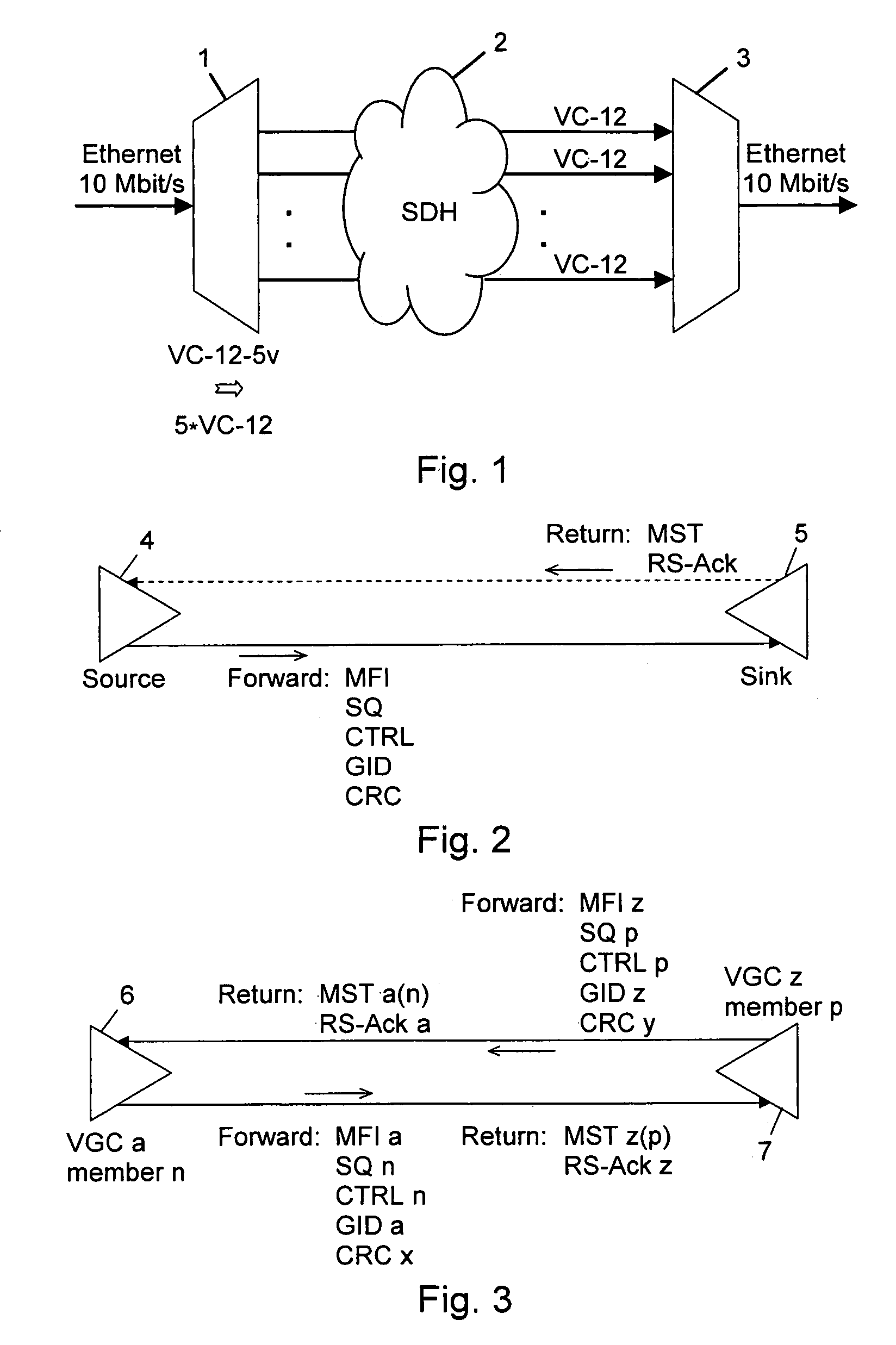
[0042]In FIG. 1 an example of the use of virtual concatenation is illustrated. Ethernet data of 10 Mbit / s are transmitted from one network element 1 through an SDH (Synchronous Digital Hierarchy) network 2 to another network element 3. For illustrational purposes the network elements are here shown as multiplexers / demultiplexers, although they comprise much additional circuitry. The 10 Mbit / s data are mapped into five VC-12 containers constituting a VCG (Virtual Concatenation Group), which can be denoted as VC-12-5v. The five containers are called the members of the VCG. As illustrated, the five VC-12 containers are transmitted as individual containers through the network. In the receiving network element 3 the containers of the VCG can be recognized on their overhead, and a differential delay caused by difference in optical path length can be compensated, so that the data of the five containers can be combined ag...


PUM


Abstract

The transport capacity of a Virtual Concatenation Group (VCG) can be reduced under control of a Link Capacity Adjustment Scheme (LCAS). The VCG comprises link members, in which payload data are transmitted. A first control message comprising a fail message (RFAIL) for a link member is transmitted from sink to source, while the sink continues reception of payload data. On reception of the first control message at the source, a second control message is transmitted comprising a message (FDNU) indicating that payload data of the link member shall not be used, and transmission of payload data is discontinued. On reception of the second control message at the sink reception of payload data is discontinued, and the link member is removed. This allows a reduction of the transport capacity of a Virtual Concatenation Group to be performed in a hitless manner, even when initiated at the sink side.

Description

RELATED APPLICATION[0001]This application claims priority under 35 U.S.C. § 119 or 365 to European Patent Application No. 04388095.4, filed Dec. 23, 2004, the entire teachings of which are incorporated herein by reference.FIELD OF THE INVENTION[0002]The invention relates to a method of reducing the transport capacity of a Virtual Concatenation Group that is transported from a source side to a sink side in a telecommunications network under control of a Link Capacity Adjustment Scheme, wherein said Virtual Concatenation Group comprises a number of link members, in which payload data to be received at the sink side can be transmitted. The invention further relates to a network element adapted to function as a sink side in a telecommunications network, and to a corresponding computer program and computer readable medium.BACKGROUND OF THE INVENTION[0003]Generic transport networks, such as OTN (Optical Transport Network), SDH (Synchronous Digital Hierarchy) or SONET (Synchronous Optical ...

Claims


Application Information

Patent Timeline
Patent Type & Authority Patents(United States)
IPC IPC(8): H04L1/16G01R31/08G06F11/00
CPCH04J3/14H04J3/1611H04J2203/0094H04J2203/0069H04J2203/006
Inventor CHRISTENSEN, ANNEGERDSTROM, FLEMMING
Owner TELLABS OPERATIONS
Why Eureka
Try Eureka