Hydraulic control apparatus for vehicular fluid-actuated power transmitting device provided with lock-up clutch

a technology of hydraulic control apparatus and transmission device, which is applied in the direction of fluid couplings, instruments, heat measurement, etc., can solve the problems of failure to improve the fuel economy of the vehicle, delay in the temperature of the working fluid, etc., and achieve the effect of preventing an excessive rise of the pressure of the working fluid

Inactive Publication Date: 2009-11-17
TOYOTA JIDOSHA KK
View PDF15 Cites 7 Cited by
  • Summary
  • Abstract
  • Description
  • Claims
  • Application Information

AI Technical Summary

Benefits of technology

[0008]The present invention was made in the light of the background art discussed above. It is therefore an object of the present invention to provide a hydraulic control apparatus for a vehicular fluid-actuated power transmitting device provided with a lock-up clutch, which hydraulic control apparatus permits a rapid rise of the temperature of the working fluid from a low level immediate after starting of a vehicle.
[0013]In the above-described mode (2), the low-temperature by-pass device includes the clutch switching valve, solenoid-operated slip control valve and control device. The control device commands the solenoid-operated slip control valve to generate the pilot pressure for opening the oil cooler by-pass valve when the lock-up clutch is placed in its released state by the clutch switching valve. The pilot pressure generated by the solenoid-operated slip control valve is applied to the oil cooler by-pass valve through the switching portion of the clutch switching valve, to open the oil cooler by-pass valve, for permitting the working fluid to by-pass the oil cooler. Thus, the solenoid-operated slip control valve is utilized to open the oil cooler by-pass valve when the temperature of the working fluid is lower than the predetermined lower limit while the lock-up clutch is in the released state. Accordingly, the number of the required components or elements of the hydraulic control device can be reduced.
[0017]In the above-described mode (4), the oil cooler by-pass valve functions to protect the oil cooler against a damage due to an excessively high pressure of the working fluid, as well as to permit the working fluid to by-pass the oil cooler when the temperature of the working fluid is lower than the predetermined lower limit.
[0019]In the above-described mode (5), the pressure-receiving surface area of the spool of the oil cooler by-pass valve, which surface area receives the fluid pressure in the fluid chamber in the valve-opening direction is larger than the surface area which receives the fluid pressure in the valve-closing direction, so that the oil cooler by-pass valve is opened when the pressure of the working fluid in the oil cooler has been raised to the predetermined upper limit or higher. Thus, the oil cooler by-pass valve not only functions to permit the working fluid to by-pass the oil cooler when the working fluid temperature is lower than the lower limit, but also functions to protect the oil cooler against a damage due to an excessively high pressure of the working fluid as in the conventional hydraulic control apparatus.
[0022]In the above-described mode (6) or (7), the temperature sensor is provided to accurately detecting the temperature of the working fluid, for assuring adequate control of the oil cooler by-pass valve to permit the working fluid to by-pass the oil cooler when the fluid temperature is lower than the lower limit.
[0024]In the above-described mode (8), the oil cooler by-pass valve is opened by the pressure of the working fluid at a temperature of the working fluid lower than the predetermined lower limit, since the biasing force of the shape-memory alloy spring is smaller than the nominal value. When the temperature of the working fluid has been raised to the lower limit or higher, the shape-memory alloy spring normally functions to produce the nominal biasing force acting on the spool in the valve-closing direction. When the pressure of the working fluid in the oil cooler has been raised to a predetermined upper limit, the spool is moved to the open position against the biasing force of the shape-memory alloy spring, to thereby preventing an excessive rise of the pressure of the working fluid in the oil cooler, whereby the oil cooler is protected against a damage due to the excessively high pressure of the working fluid. Further, the low-temperature by-pass device can be easily provided by simply providing the oil cooler by-pass valve with the shape-memory alloy spring, namely, by merely replacing the conventional spring with the shape-memory alloy spring.

Problems solved by technology

Accordingly, the rise of the working fluid temperature is delayed after starting of the vehicle, unfavorably resulting in a failure to improve the fuel economy of the vehicle.

Method used


Image

  • Hydraulic control apparatus for vehicular fluid-actuated power transmitting device provided with lock-up clutch
  • Hydraulic control apparatus for vehicular fluid-actuated power transmitting device provided with lock-up clutch
  • Hydraulic control apparatus for vehicular fluid-actuated power transmitting device provided with lock-up clutch

Examples


first embodiment

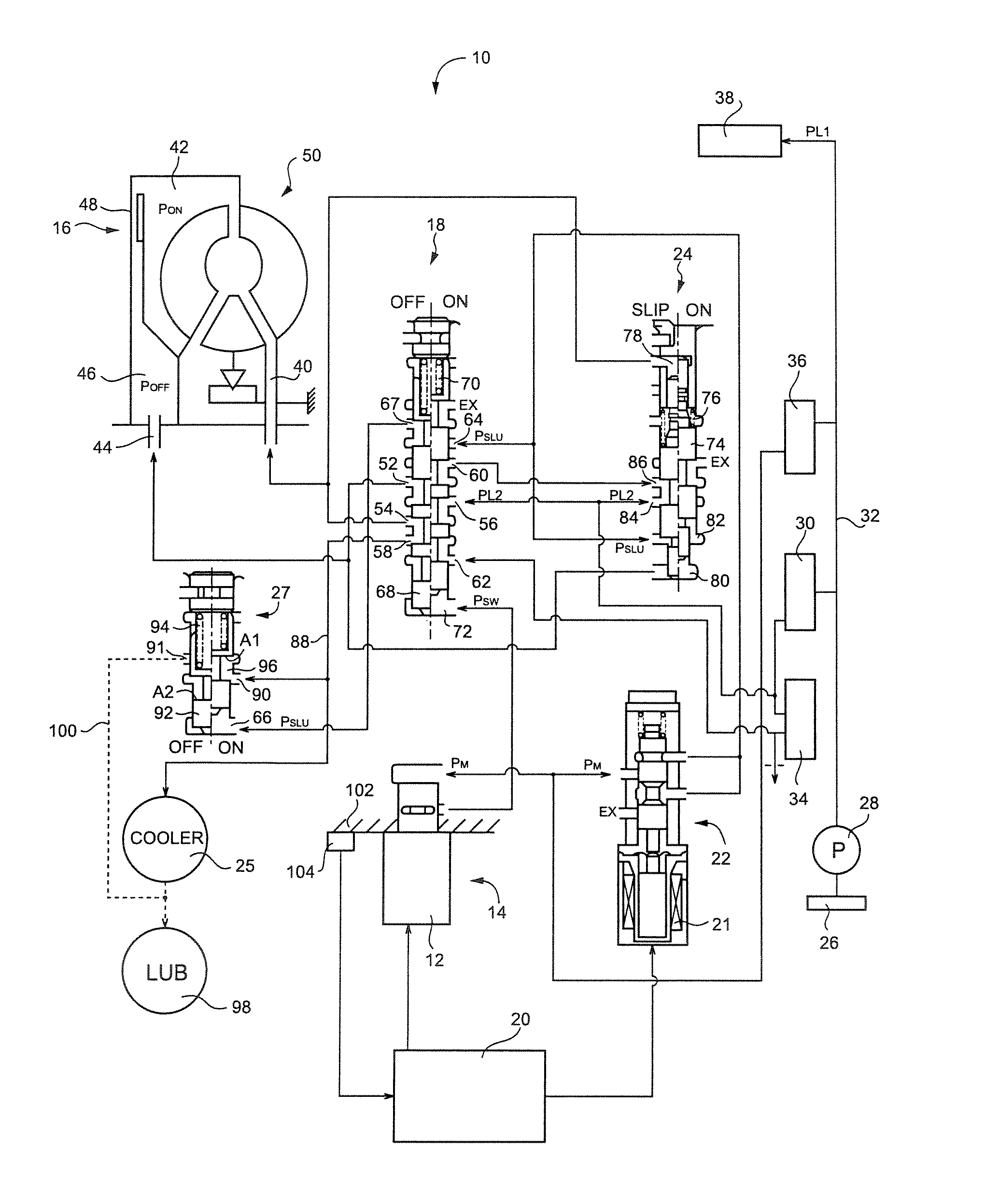
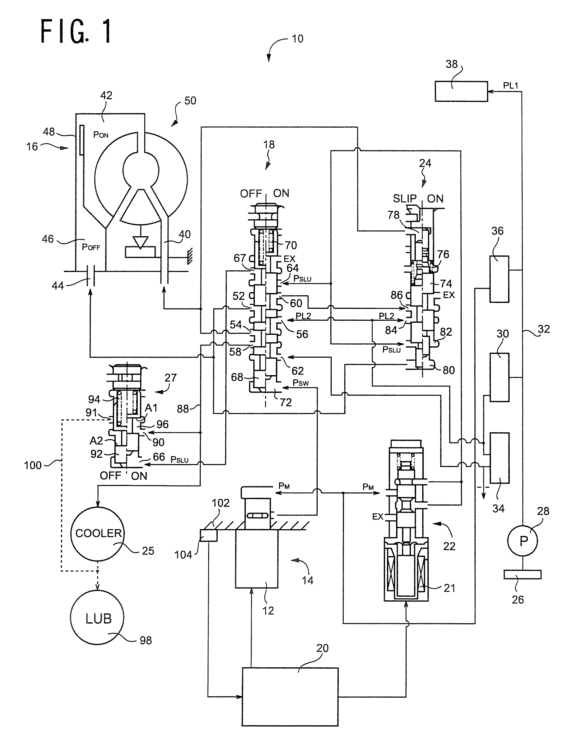
[0031]Referring first to FIG. 1, there are shown a hydraulic control circuit 10 and an electronic control device 20 which cooperate with each other to provide a hydraulic control apparatus constructed according to this invention, to control a vehicular fluid-actuated power transmitting device in the form of a torque converter 50 provided with a lock-up clutch 16. The torque converter 50 is disposed between an engine and an automatic transmission (not shown) of an automotive vehicle.

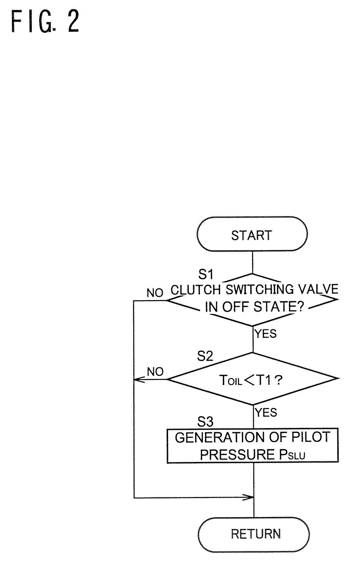
[0032]The hydraulic control circuit 10 includes: a solenoid-operated switching valve 14 provided with a switching solenoid 12 which is energized to generate a switching pilot pressure PSW; a clutch switching valve 18 operable according to the switching pilot pressure PSW, between a releasing position (OFF position) for placing the lock-up clutch 16 in its released state, and an engaging position (ON position) for placing the lock-up clutch 16 in its engaged state; a solenoid-operated slip control valve 22...

second embodiment

[0056]The hydraulic control circuit 110 is different from the hydraulic control circuit 10, only in that the hydraulic control circuit 110 further includes a solenoid-operated switching valve 112. In this second embodiment, the oil cooler by-pass valve 27 is controlled according to the switching pilot pressure PSW generated by the solenoid-operated switching valve 112 under the control of the electronic control device 20. The switching valve 112 has a solenoid energized and de-energized by the electric control device 20. When the solenoid 12 of the solenoid-operated switching valve 112 is in its de-energized or off state, the modulated pressure PM generated by the second supply portion 116 is not applied as the switching pilot pressure PSW from the switching valve 112 to the fluid chamber 66 of the oil cooler by-pass valve 27. When the same solenoid is in its energized or on state, the modulated pressure PM is applied as the switching pilot pressure PSW from the switching valve 112 ...

third embodiment

[0059]FIG. 4 shows a hydraulic control circuit 130 which cooperates with the electronic control device 20 (shown in FIG. 1 but not shown in FIG. 3) to provide a hydraulic control apparatus for the fluid-actuated power transmitting device in the form of the torque converter 50 provided with the lock-up clutch 16, which hydraulic control apparatus is constructed according to the present invention. In FIG. 3, the electronic control device 20, strainer 26, pressure regulating valves 30, 34, 36, etc. are not shown, but the hydraulic control circuit 130 includes the strainer, pressure regulating valves 30, 34, 36 and other hydraulic components shown in FIG. 1, and is controlled by the electronic control device 20.

[0060]The hydraulic control circuit 130 is different from the hydraulic control circuit 10, only in that the hydraulic control circuit 130 includes an oil cooler by-pass valve 132, which does not receive the pilot pressure PSLU from the solenoid-operated slip control valve 22 or ...


PUM


Abstract

A hydraulic control apparatus for a vehicular fluid-actuated power transmitting device provided with a lock-up clutch and an oil cooler, the lock-up clutch being operable between an engaged state and a released state according to a difference between pressures of a working fluid in an engaging fluid chamber and a releasing fluid chamber, the oil cooler being connected to a fluid passage communicating with the engaging and releasing fluid chambers, and operable to cool the working fluid, the hydraulic control apparatus including an oil cooler by-pass valve operable to permit the working fluid to by-pass the oil cooler, and a low-temperature by-pass device operable to open the oil cooler by-pass valve, for permitting the working fluid to by-passes the oil cooler, when a temperature of the working fluid is lower than a predetermined lower limit.

Description

[0001]The present application is based on Japanese Patent Application No. 2006-035869 filed Feb. 13, 2006, the contents of which are incorporated herein by reference.BACKGROUND OF THE INVENTION[0002]1. Field of the Invention[0003]The present invention relates in general to a hydraulic control apparatus for a vehicular fluid-actuated power transmitting device provided with a lock-up clutch, and more particularly to improvements of a cooler by-pass valve used in the hydraulic control apparatus.[0004]2. Discussion of the Related Art[0005]In the field of an automotive vehicle including a fluid-actuated power transmitting device such as a torque converter or fluid coupling provided with a lock-up clutch, there is known a hydraulic control apparatus arranged to place the lock-up clutch in a slipping state for absorbing a periodic torque variation of an engine of the vehicle during running of the vehicle at a relatively low speed. A hydraulic control apparatus 200 shown in FIG. 5 is an exa...

Claims


Application Information

Patent Timeline
Patent Type & Authority Patents(United States)
IPC IPC(8): F16D39/00G01K1/14
CPCF16H59/72F16H61/143Y10T74/19149Y10T137/6552
Inventor FUKUSHIMA, HIROSHIKATO, NAOKITSUCHIDA, KENICHI
Owner TOYOTA JIDOSHA KK
Why Eureka
Try Eureka