Methods and systems for in-situ machinery inspection

a technology of rotating machinery and optical inspection, which is applied in the direction of instruments, tubes with screens, image-conversion/image-amplification tubes, etc., can solve the problems of high cost of gas and steam turbines for electrical power generation, components within the machine can only be inspected, and the disassembly of the turbine to inspect it is an expensive process

Inactive Publication Date: 2009-11-17
GENERAL ELECTRIC CO
View PDF19 Cites 27 Cited by
  • Summary
  • Abstract
  • Description
  • Claims
  • Application Information

AI Technical Summary

Problems solved by technology

For example, gas and steam turbines for electrical power generation are very expensive and are often not removed from service for inspection or maintenance unless absolutely necessary.
However, components within the machine typically can only be inspected while the machine is offline and in some cases at least partially disassembled.
Disassembling a turbine to inspect it is an expensive process and takes the turbine out of service for a significant amount of time.
Because none of the foregoing techniques are suitable for inspection while the turbine is on-line and running under load, other turbine inspection techniques are used in an attempt to monitor machine components during full load operation.
The interior environment of a turbine is hostile for electrical sensing equipment.
High pressures and reactive chemistry within turbines provide further detriment to inspection and measurement equipment.

Method used


Image

  • Methods and systems for in-situ machinery inspection
  • Methods and systems for in-situ machinery inspection
  • Methods and systems for in-situ machinery inspection

Examples


Embodiment Construction

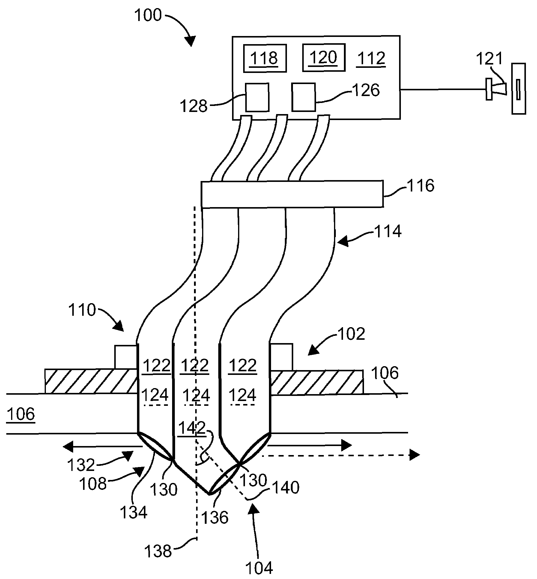
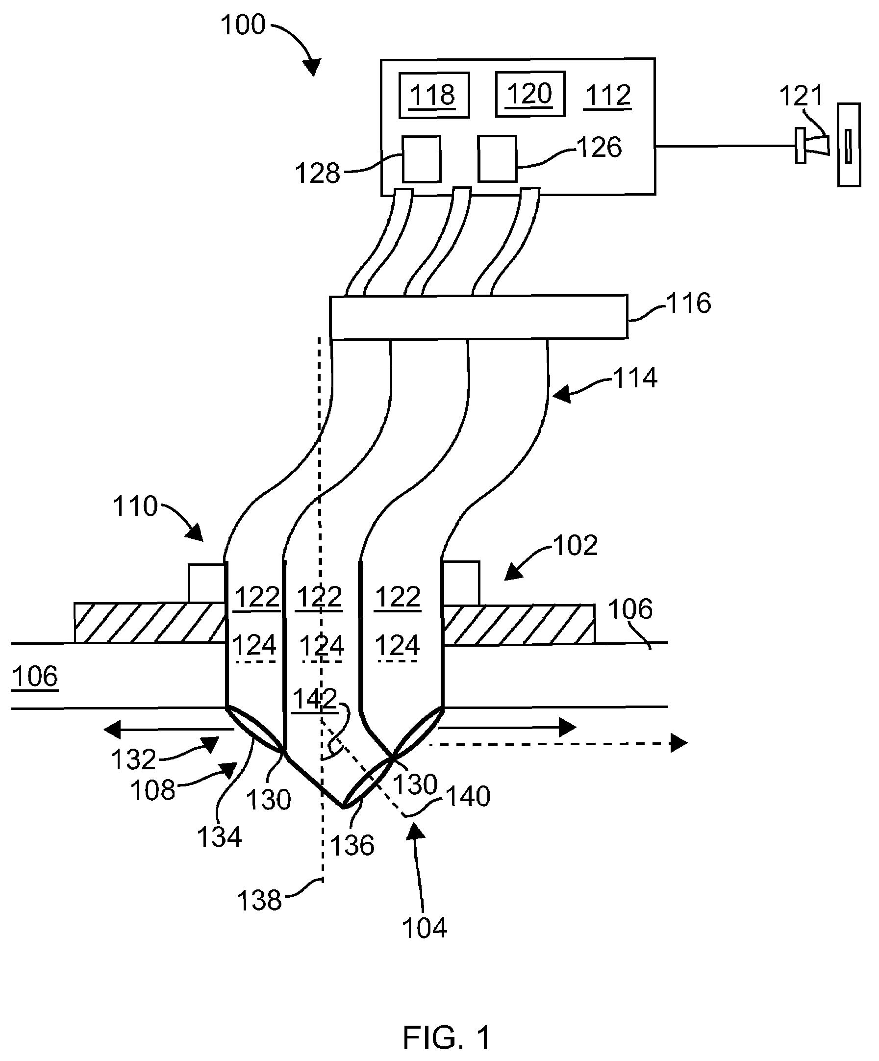
[0012]The following detailed description illustrates the disclosure by way of example and not by way of limitation. The description clearly enables one skilled in the art to make and use the disclosure, describes several embodiments, adaptations, variations, alternatives, and uses of the disclosure, including what is presently believed to be the best mode of carrying out the disclosure. The disclosure is described as applied to a preferred embodiment, namely, a process of inspecting internal components of a rotatable machine during operation. However, it is contemplated that this disclosure has general application to inspecting components located in hostile environments of machinery during all phases of operation.

[0013]While the methods and systems are herein described in the context of a gas turbine engine and a steam turbine used in an industrial environment, it is contemplated that the method and apparatus described herein may find utility in other rotating machinery such as moto...


PUM

PropertyMeasurementUnit
temperaturesaaaaaaaaaa
acquisition timeaaaaaaaaaa

Abstract

Methods and systems for inspecting rotatable machine components are provided. The system includes a fiber optic port configured to extend through a first aperture of a machine casing wherein the port includes an interior end and an exterior end. The system further includes an imager configured to optically couple to the exterior end. The imager includes a light intensifier capable of generate images of inspection components though the port using ambient light. The imager further includes an image capture gate configured to control an acquisition time of the generated images.

Description

BACKGROUND OF THE INVENTION[0001]This invention relates generally to inspection of rotating machinery components, and more particularly, to methods and systems for optical inspection of rotating machinery components.[0002]At least some known large machines achieve an optimal efficiency of operation when the machine is maintained operating on-line. For example, gas and steam turbines for electrical power generation are very expensive and are often not removed from service for inspection or maintenance unless absolutely necessary. However, components within the machine typically can only be inspected while the machine is offline and in some cases at least partially disassembled. Known conventional methods of inspecting for example, turbine blades such as surface inspection methods (i.e., magnetic particle testing; eddy current testing; dye penetrant techniques) and volumetric methods (i.e., ultrasonic testing) rely on the periodic disassembly of the turbine. Disassembling a turbine to...

Claims


Application Information

Patent Timeline
Patent Type & Authority Patents(United States)
IPC IPC(8): G01N21/00H01L27/00G01M99/00
CPCG02B23/2484G02B23/2492F01D21/003G02B23/26F05D2260/80
Inventor OGBURN, ERIK MATTHEWGILCHRIST, III, GEORGE MARTIN
Owner GENERAL ELECTRIC CO
Why Eureka
Try Eureka