
Fiber optic telecommunications card with energy level monitoring

Active Publication Date: 2009-11-17
OYSTER OPTICS
View PDF76 Cites 12 Cited by
  • Summary
  • Abstract
  • Description
  • Claims
  • Application Information

AI Technical Summary

Benefits of technology

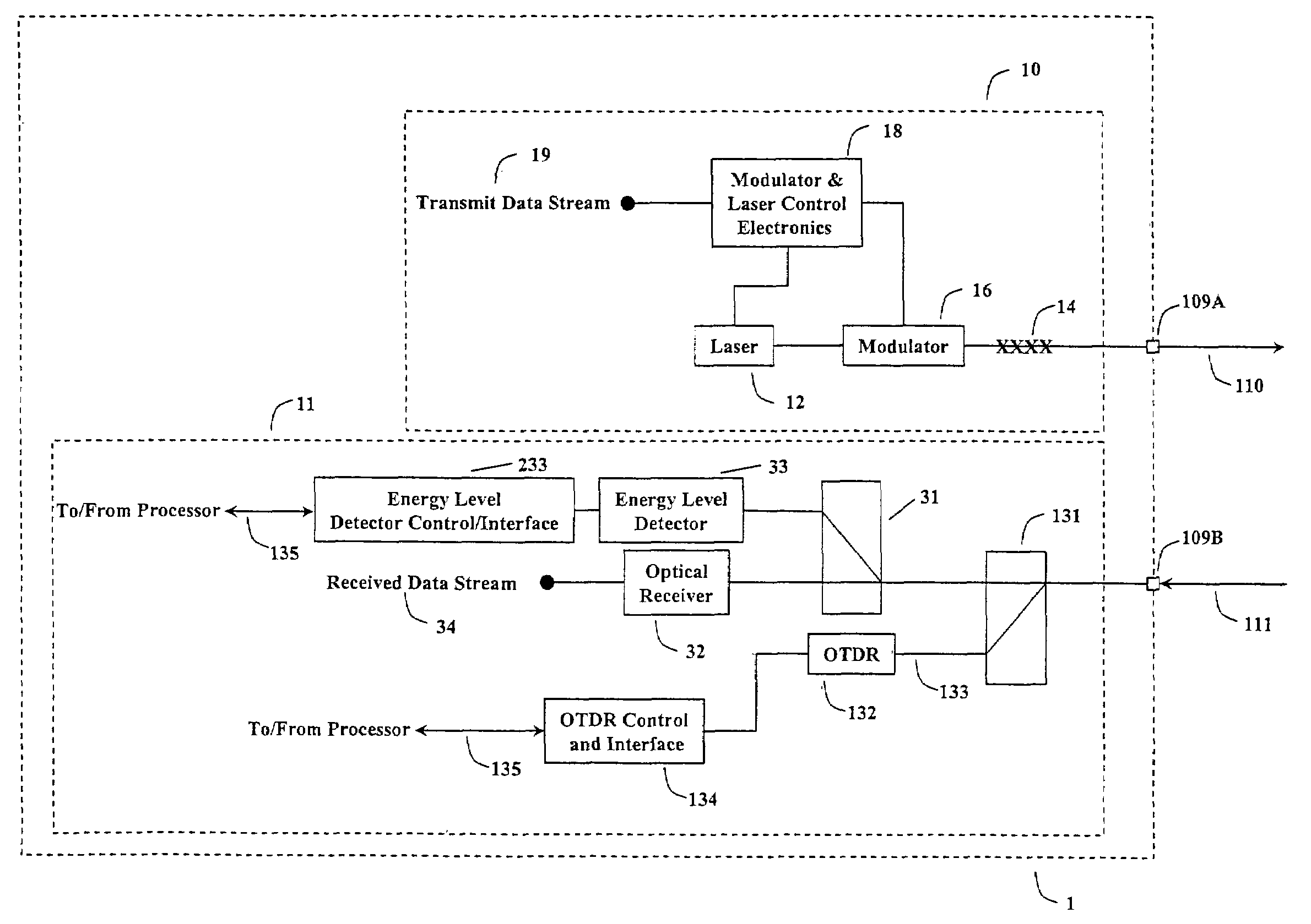
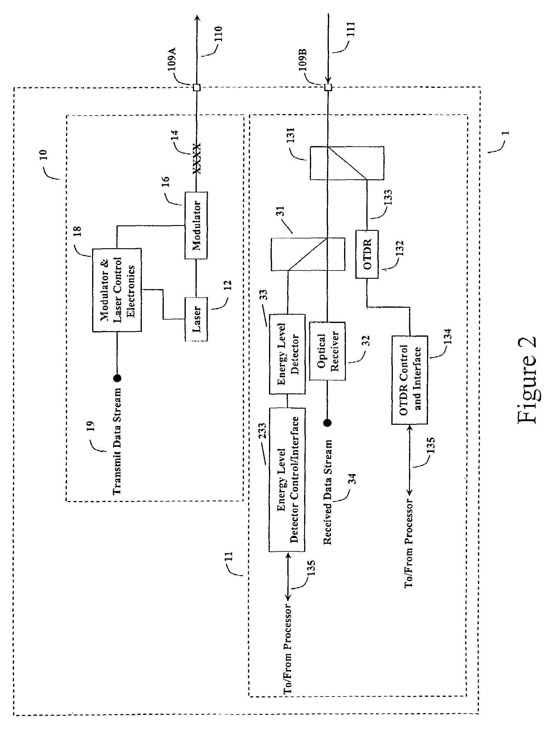
[0017]The present invention provides a transceiver card for transmitting data over a first optical fiber and receiving data over a second optical fiber, the card having a transmitter for transmitting data over the first optical fiber and a receiver for receiving data from the second optical fiber, and an OTDR connected optically to the second optical fiber upstream from the receiver. Preferably, the OTDR operates at a wavelength that is different than the wavelength used for data transmission and is connected in the optical circuit via a wavelength division multiplexed coupler. By operating the OTDR at a wavelength different than the wavelength used for data transmission, the OTDR may be allowed to continuously operate without disruption of the data traffic.
[0020]The transceiver card of the present invention preferably has fiber span length ranges for operation that are compatible with standard optical multiplexor operation, for example, two to twenty kilometers or ten to one hundred kilometers. The OTDR and energy level detector must have a measurement dynamic range that ensures proper operation over the span length limits of the transceiver card. By specifying fiber span length ranges for the OTDR and energy detector enhanced transceiver, the cost of implementation of the OTDR and energy level detector can be optimized with span length thus providing an optimized cost of implementation benefit to the customer.

Problems solved by technology

Existing amplitude modulated systems have the disadvantage that the fiber can be easily tapped and are not secure.
The Sagnac-interferometer-based systems described in these patents have the disadvantage that they require the light to travel over a loop, whether back and forth in a single fiber or over a long length looped fiber.
As a result, either the link budget for the single fiber must be doubled, reducing the data carrying capacity for a single fiber, or else a looped fiber with significant and expensive extra length of at least twice that of a single fiber must be laid between the transmitter and the receiver.
The Sagnac-interferometer-based systems thus are expensive to build and operate, and do not work particularly well with existing multiplexors or card formats.
These detectors however are expensive and must be applied to the fiber away from the box.

Method used


Image

  • Fiber optic telecommunications card with energy level monitoring
  • Fiber optic telecommunications card with energy level monitoring
  • Fiber optic telecommunications card with energy level monitoring

Examples


Embodiment Construction

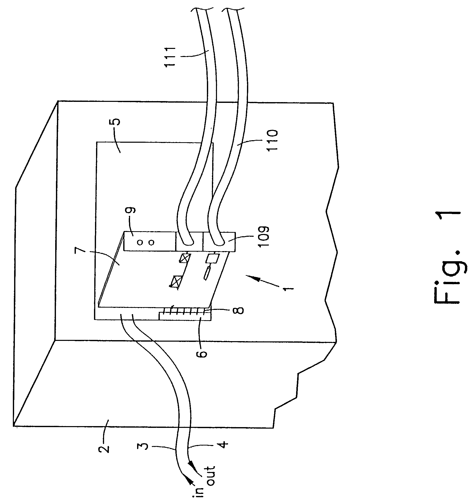
[0038]FIG. 1 shows an existing telecommunications box 2, for example a multiplexor, refitted with a card 1 of the present invention. Box 2 has an electronic data input 3 and output 4, which connect to a motherboard 5 of the box 2. Motherboard 5 includes a bus 6 for connecting existing amplitude-based cards to the motherboard 5, and connects the input 3 and output 4, through for example, data conversion circuitry, to the bus 6. The type of bus 6 is dependent upon the box manufacturer, and different types of boxes, motherboards and buses are well known in the art. Card 1 of the present invention includes electrical connections 8 to fit into bus 6.

[0039]Card 1 also includes a faceplate 9 and a backplane 7, which preferably is a printed circuit board. Faceplate 9 may be perpendicular to backplane 7 and be flush with a front side of box 2.

[0040]Faceplate 9 may have a fiber connector 109, such as a duplex SC connector, for connecting to an output fiber 110 and an input fiber 111. Alternat...


PUM


Abstract

A transceiver card for a telecommunications box for transmitting data over a first optical fiber and receiving data over a second optical fiber. The card has transmitter for transmitting data over the first optical fiber, the transmitter having a laser and a modulator, a fiber output optically connected to the laser for connecting the first optical fiber to the card, a fiber input for connecting the second optical fiber to the card, a receiver optically connected to the fiber input for receiving data from the second optical fiber, and an OTDR optically connected between the transmitter and the fiber output or between the receiver and the fiber input. An energy level detector is also provided between the receiver and the fiber input.

Description

[0001]Priority to U.S. Provisional Application No. 60 / 303,932, filed Jul. 9, 2001 and hereby incorporated by reference herein, is claimed.BACKGROUND OF THE INVENTION[0002]1. Field of the Invention[0003]The present invention relates generally to telecommunications and more particularly to transmitters and receivers for fiber optic networks.[0004]2. Background Information[0005]In current fiber optic networks, an electronic data stream is fed to an optical fiber multiplexor, which is also called “a box” in the industry. Each multiplexor runs on a specific transmission standard, for example, SONET. A laser and an amplitude modulation circuit for the laser typically are located on a card, which fits into the box. The laser amplitude modulator typically pulses or alters the laser output to create an amplitude-modulated optical signal representative of the electronic data stream. The laser amplitude modulator and laser thus define a transmitter for transmitting the optical signal over an o...

Claims


Application Information

Patent Timeline
IPC IPC(8): H04B10/00G02BH04B10/08H04B10/12
CPCH04B10/071H04B10/07955H04B10/0705H04B10/85
Inventor SNAWERDT, PETER
Owner OYSTER OPTICS
Learn More