Pallet exchanging device

a technology pallet support unit, which is applied in the direction of charging, lighting and heating apparatus, furniture, etc., can solve the problems of limited working space secured by revolving arm, inability of pallet exchanging device to cope with multi-phase pallet exchanging system, and limited arm length, so as to achieve sufficient working space, improve machining efficiency, and shorten the moving distance of the pallet supporting unit

Inactive Publication Date: 2009-11-24
OKUMA CORP
View PDF10 Cites 25 Cited by
  • Summary
  • Abstract
  • Description
  • Claims
  • Application Information

AI Technical Summary

Benefits of technology

[0020]According to the present invention, the pallet supporting unit is movable between the first position where the pallets are exchanged in the working machine main body and a second position where the pallet is delivered and received at the delivery position of the pallet storage device, and the space can be provided on the front side of the work carry-in port by the movement to the second position. Accordingly, when a worker desires to perform a maintenance operation via the work carry-in port of the working machine main body, the working space can be secured on the front side of the work carry-in port by the movement of the pallet supporting unit to the second position. Therefore, when the invention is compared with the device which is proposed by the same applicant of the invention, the working space sufficient for the worker can be certainly secured on the front side of the work carry-in port, which is convenient.
[0021]Further, according to the present invention, the pallet exchanging device includes the pallet storage device having a plurality of pallet holders for holding pallets. In the pallet storage device, any pallet holder can be brought to a delivery position for delivering and receiving a pallet to / from the pallet supporting unit. Therefore, the operation for preparing the pallet on which the work to be machined next is placed can be efficiently performed during the machining in the working machine main body, and the machining efficiency can be improved. Further, when the present invention is compared with the conventional device which does not perform the operation for bringing to the pallet delivery position, the moving distance of the pallet supporting unit can be shortened, thereby downsizing the device itself and shortening the time required for the exchange.

Problems solved by technology

As described above, when the pallet exchanging device is provided to the front side of the working machine main body, it is a problem of securing a working space for a worker in front of the working machine main body.
However, since the length of the arm is limited in view of strength, the working space which is secured by revolving the arm is also limited.
Since the arm can slide only to the front-rear direction with respect to the working machine, the pallet exchanging device cannot cope with a multi-phase pallet exchanging system described in the Japanese Utility Model Laid-Open No. 6-63252.
On the other hand, in the pallet exchanging device 51 described in the Japanese Utility Model Laid-Open No. 6-63252, although the sufficient working space can be secured on the front side of the working machine main body, since the works W, W . . . are stored to be arranged in the right-left direction in the work storage rack 57, the rail 52 for sliding the movable platen 53 should be projected to the right-left direction, thereby arising a problem such that the device becomes large.

Method used


Image

  • Pallet exchanging device
  • Pallet exchanging device
  • Pallet exchanging device

Examples


Embodiment Construction

[0034]A pallet exchanging device according to one embodiment of the present invention is explained below with reference to drawings.

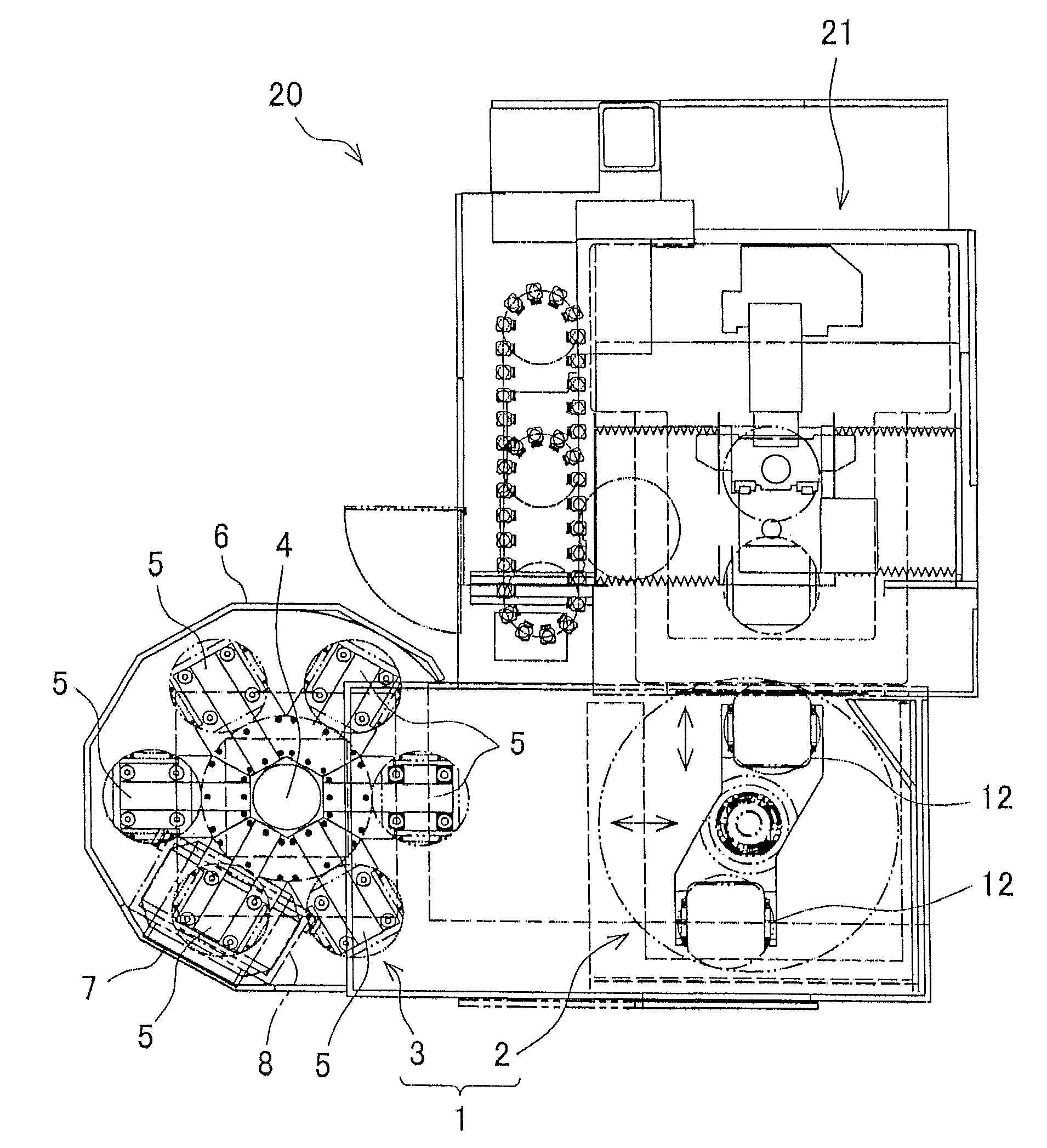
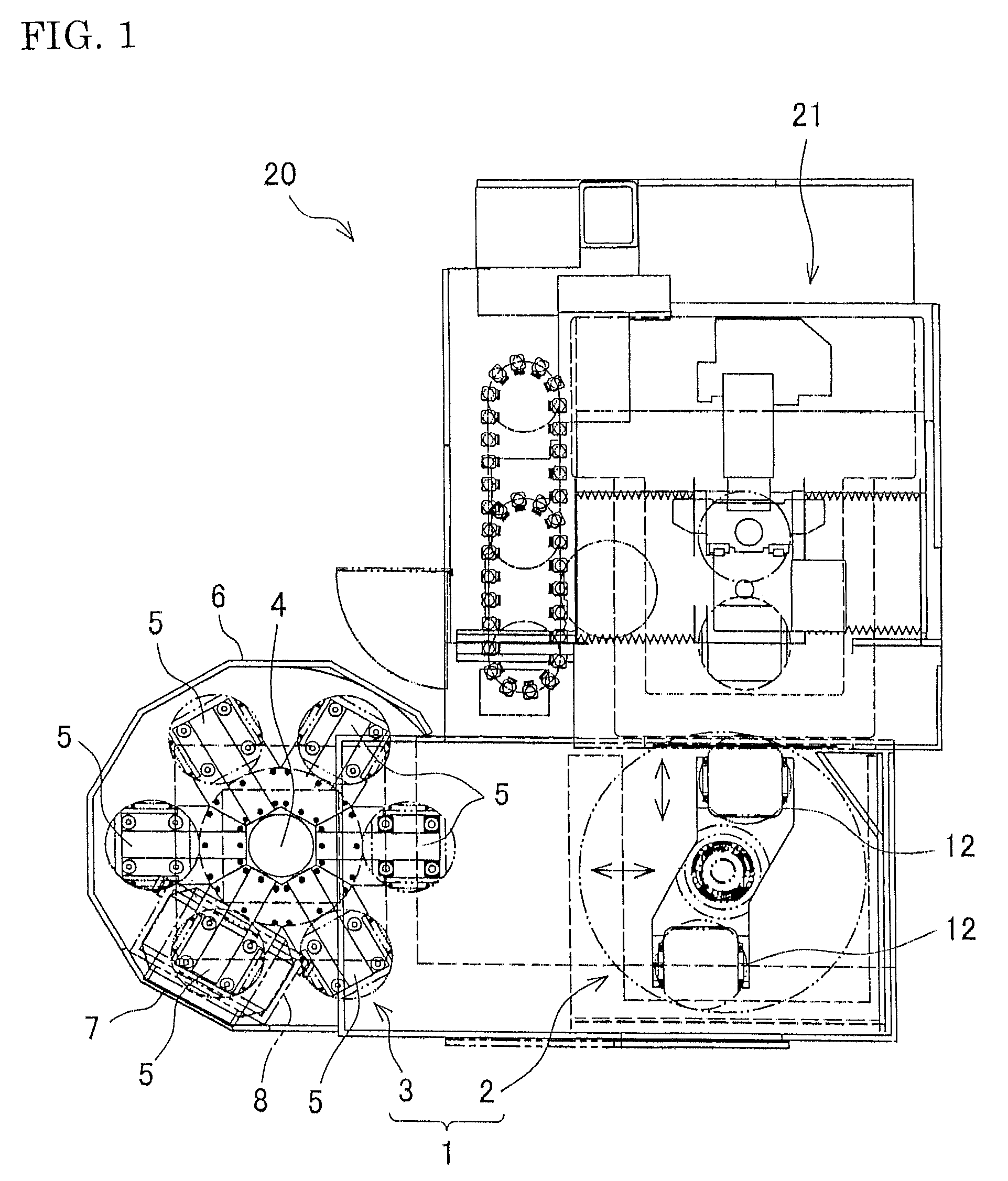
[0035]FIG. 1 is an explanatory diagram illustrating a working machine 20 having the pallet exchanging device 1 according to this embodiment viewed from above. FIG. 2 is an explanatory diagram illustrating the working machine 20 viewed from the side. FIG. 3 is a perspective explanatory diagram illustrating a main body 21 of the working machine 20. An up-down direction in FIG. 1 will be described as a front-rear direction of the working machine 20 in the description.

[0036]The working machine 20 is constituted so as to include the working machine main body 21 as a 5-axis control vertical machining center and the pallet exchanging device 1. The pallet exchanging device 1 is installed on the front side of the working machine main body 21 and has an arm (pallet supporting unit) 2 and a pallet stocker (pallet storage device) 3 as mentioned later.

[0037]The work...


PUM

PropertyMeasurementUnit
lengthaaaaaaaaaa
strengthaaaaaaaaaa
sizeaaaaaaaaaa

Abstract

A pallet exchanging device is provided which can secure a sufficient working space and can cope with a multi-phase pallet exchanging system without increasing the size of the device. In a pallet exchanging device, a pallet stocker is constituted so that any pallet placing pedestal can be brought to a delivery position where a pallet is delivered and received to / from an arm, and the arm can be moved between a first position where pallets are exchanged in the working machine main body and a second position where a pallet is delivered and received at the delivery position of the pallet stocker. When the arm is moved to the second position, a space for a worker is provided on a front side of a work carry-in port.

Description

BACKGROUND OF THE INVENTION[0001]This application claims the benefit of Japanese Patent Application Number 2006-150498 filed on May 30, 2006, the entirety of which is incorporated by reference.[0002]1. Field of the Invention[0003]The present invention relates to a pallet exchanging device which is installed in front of a working machine such as a vertical machining center and exchanges pallets on which works are placed.[0004]2. Description of the Related Art[0005]Conventionally, working machines such as a vertical machining center are provided with a pallet exchanging device, which exchanges a pallet which is provided in a standby position and on which a work before machining is placed (hereinafter, pre-machining pallet) and a pallet which is provided in an exchanging position (or machining position) and on which a machined work is placed (hereinafter, post-machining pallet), in proximity positions.[0006]Such a pallet exchanging device includes a device disclosed in Japanese Patent ...

Claims


Application Information

Patent Timeline
Patent Type & Authority Patents(United States)
IPC IPC(8): B23P23/00
CPCB23Q1/4852B23Q7/1431Y10T29/5196
Inventor KAWAI, SUMIOMURATA, ATSUYAYAMAO, MICHIO
Owner OKUMA CORP
Why Eureka
Try Eureka