Electric power steering apparatus

a technology of electric steering and electric motor, which is applied in the direction of electric steering, power steering steering, vehicle components, etc., can solve the problems of large size of the apparatus, low reliability of electrical connections, and high cost, and achieve the effect of reducing size and cost and improving reliability of electrical connections

Inactive Publication Date: 2009-11-24
MITSUBISHI ELECTRIC CORP
View PDF22 Cites 22 Cited by
  • Summary
  • Abstract
  • Description
  • Claims
  • Application Information

AI Technical Summary

Benefits of technology

[0008]Accordingly, the present invention is intended to obviate the problem as referred to above, and has its object to provide an electric power steering apparatus which can be reduced in size and cost, and improved in reliability of electrical connections by constructing a power board, a high current board and a control board by the use of a single substrate.
[0010]According to the electric power steering apparatus of the present invention, the power main body and the control main body are mounted on the single metal substrate, so the apparatus can be reduced in size and cost, and the reliability of electrical connections can be improved.

Problems solved by technology

As a result, there arises a problem that the apparatus becomes large in size, high in cost, and low in reliability of electrical connections.

Method used


Image

  • Electric power steering apparatus
  • Electric power steering apparatus
  • Electric power steering apparatus

Examples


embodiment 1

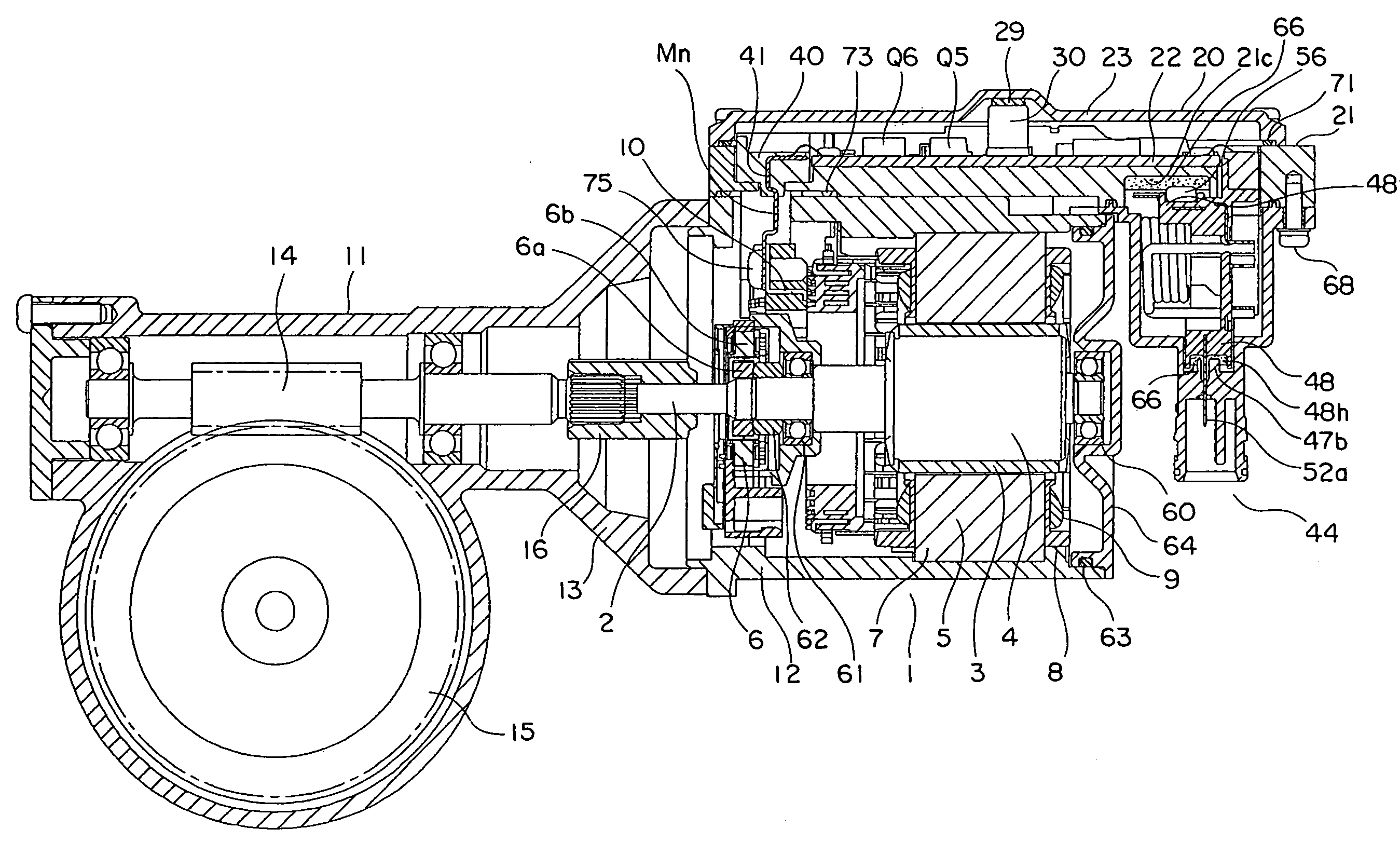
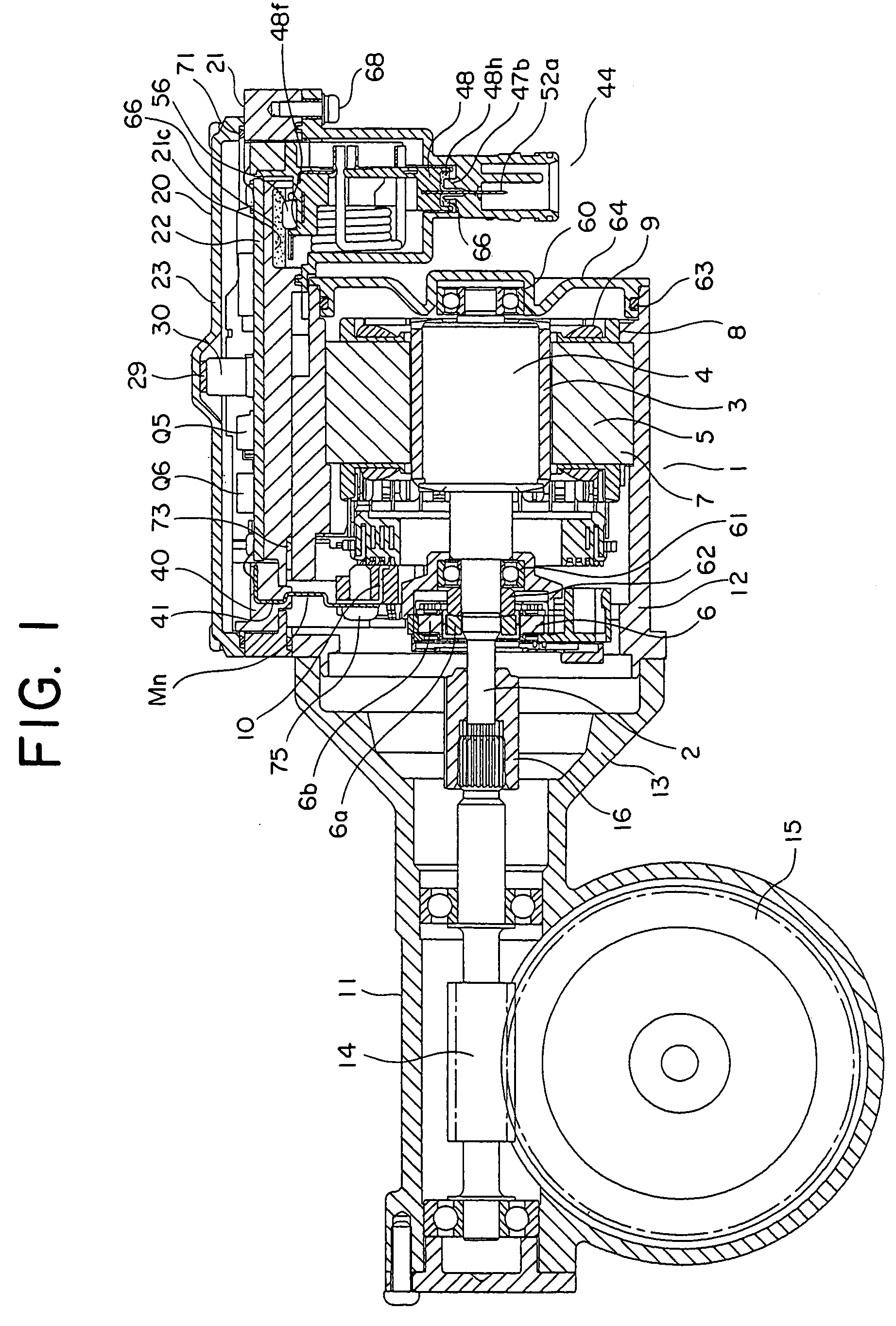
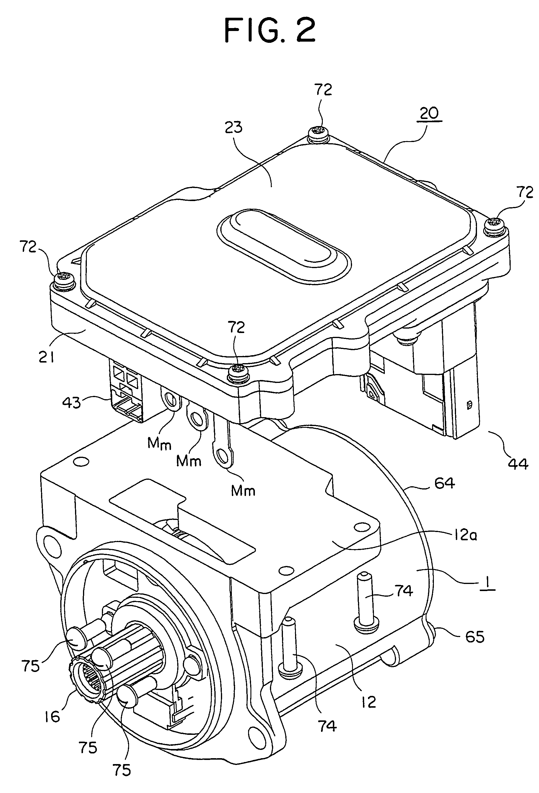
[0023]FIG. 1 is a cross sectional view that shows an electric power steering apparatus according to a first embodiment of the present invention. FIG. 2 is an exploded perspective view that shows the electric power steering apparatus in FIG. 1, and FIG. 3 is an exploded perspective view that shows a control unit 20 in FIG. 2.

[0024]In these figures, an electric motor 1 in the form of a three-phase brushless motor of this electric power steering apparatus is provided with an output shaft 2, a rotor 4 with a permanent magnet 3 having eight magnetic poles fixedly attached to the output shaft 2, a stator 5 arranged around the rotor 4, and a rotational position sensor 6 arranged at an output side of the output shaft 2 for detecting the rotational position of the rotor 4.

[0025]The stator 5 has twelve salient poles 7 arranged in opposition to the outer periphery of the permanent magnet 3, insulators 8 attached to these salient poles 7, respectively, and armature windings 9 of three phases U,...

embodiment 2

[0133]FIG. 9 is a cross sectional view showing an electric power steering apparatus according to a second embodiment of the present invention. FIG. 10 is an exploded perspective view that shows a control unit 20 of FIG. 9.

[0134]In this second embodiment, the housing 12 of the electric motor 1 and the heat sink 21 of the control unit 20 of the first embodiment are integrated with each other to provide a housing 80. The other construction of the second embodiment is similar to that of the electric power steering apparatus of the first embodiment.

[0135]In this second embodiment, the housing 80 is formed with a planar portion 80a at a side surface thereof that is in parallel to an axis of an electric motor 1. A metal substrate 22 is arranged on the planar portion 80a, and fixedly attached thereto by means of screws 70. A frame 40 is also fixedly attached to the housing 80 by means of the screws 70.

[0136]The motor terminals Mm and the sensor connector 43 are inserted into a hole 80b form...


PUM


Abstract

A control unit including a plurality of boards is formed of a single multilayer metal substrate, whereby an electric power steering apparatus can be obtained in which connection members for connecting between the boards are made unnecessary, so the size and cost of the apparatus can be reduced, and the reliability of bonding can be improved. In the electric power steering apparatus, a power main body (20a) and a control main body (20b) are mounted on a metal substrate (22), and the power main body (20a) and the control main body (20b) are electrically connected to each other by wiring patterns (26a through 26e) and metal columns 28a through 28d in the metal substrate 22.

Description

BACKGROUND OF THE INVENTION[0001]1. Field of the Invention[0002]The present invention relates to an electric power steering apparatus equipped with an electric motor for outputting assist torque to the steering wheel of a vehicle, and a control unit for controlling the driving of the electric motor.[0003]2. Description of the Related Art[0004]In the past, there has been known an electric power steering apparatus which is equipped with an electric motor for outputting assist torque to the steering wheel of a vehicle, and a control unit mounted on the electric motor for controlling the driving of the electric motor (see, for example, a first patent document (Japanese patent No. 3638269).[0005]This electric power steering apparatus includes a power board on which a bridge circuit is mounted for switching the current of the electric motor, a control board on which a microcomputer is mounted for generating a drive signal to control the bridge circuit, and a high current board on which a ...

Claims


Application Information

Patent Timeline
Patent Type & Authority Patents(United States)
IPC IPC(8): B62D5/04
CPCB62D5/0406B60Y2400/307B60Y2410/124B62D5/0409B62D5/0463
Inventor TOMINAGA, TSUTOMUHOHTANI, TOHRUYAMAGUCHI, YASUSHIFUJIMOTO, TADAYUKI
Owner MITSUBISHI ELECTRIC CORP
Why Eureka
Try Eureka