Bone recovery device

a bone recovery and bone technology, applied in non-surgical orthopedic devices, medical science, dentistry, etc., can solve the problems of not always effective, insufficient bone recovery volume, and inability to guarantee the absence of graft rejection so readily, and achieve the effect of effective bone recovery, improved recovery capacity and ease of use, and easy compliance with hygiene conditions

Inactive Publication Date: 2009-11-24
ANTHOGYR SAS
View PDF12 Cites 14 Cited by
  • Summary
  • Abstract
  • Description
  • Claims
  • Application Information

AI Technical Summary

Benefits of technology

[0011]An object of the present invention is to avoid the drawbacks of prior art bone recovery devices by proposing a new structure that assures effective bone recovery and allows a plurality of successive uses by emptying the filter several times and returning it to an aspiration position without demounting it. As a result, hygiene conditions may easily be complied with whilst the recovery capacity and the ease of use are considerably increased.
[0026]This constitutes a simple way both to retain the filter in the axial main body and to free up the annular cavity around the filter.
[0029]The diameter of the axial passage in the front connector is preferably substantially the same as the inside diameter of the filter. As a result, a canula may be inserted axially and at the same time into the front connector and into the distal end region of the filter. This also facilitates emptying the filter by sliding the piston after removing the canula.

Problems solved by technology

This is not always effective, and the volume of bone recovered is not always sufficient.
Such materials, although developed for this specific purpose, do not guarantee so readily the absence of graft rejection.
Thus, during drilling operations, bone debris are aspirated and lost in the general filtration system of the dentist's chair.
This requires relatively complex manipulations and in particular demounting of the device, which does not guarantee satisfactory hygiene.
Moreover, there is no provision for replacing the filter conveniently and satisfactorily in the device to carry out a plurality of successive bone recovery operations on the same patient.
The recovery capacity is therefore limited.

Method used


Image

  • Bone recovery device
  • Bone recovery device
  • Bone recovery device

Examples


Embodiment Construction

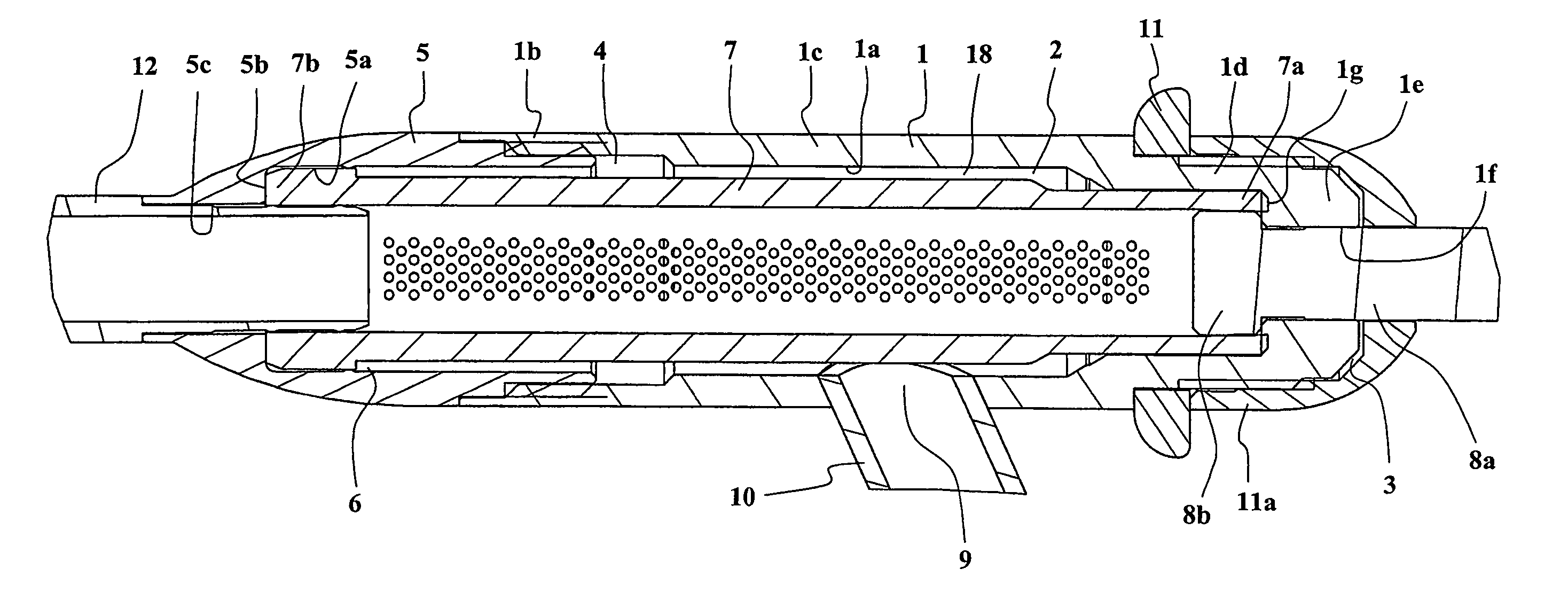
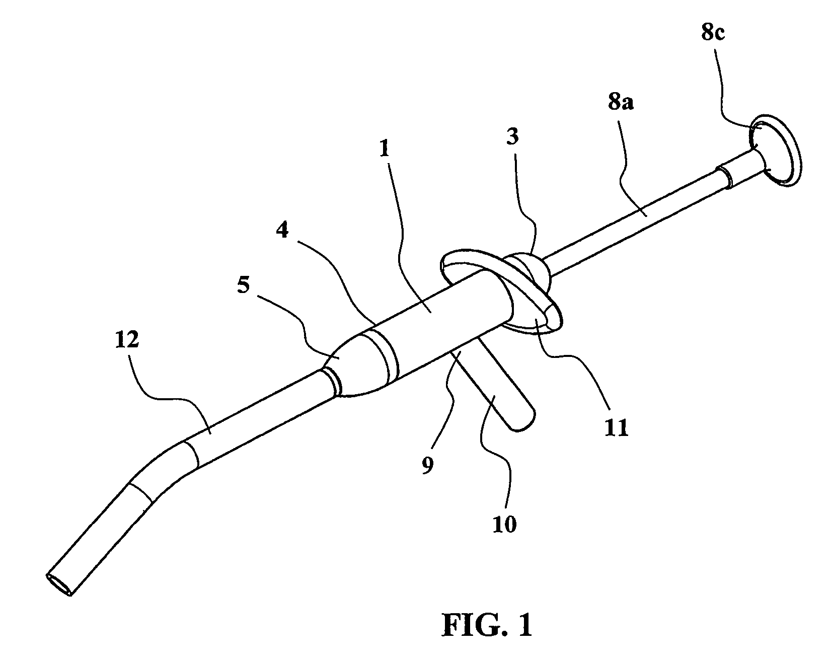
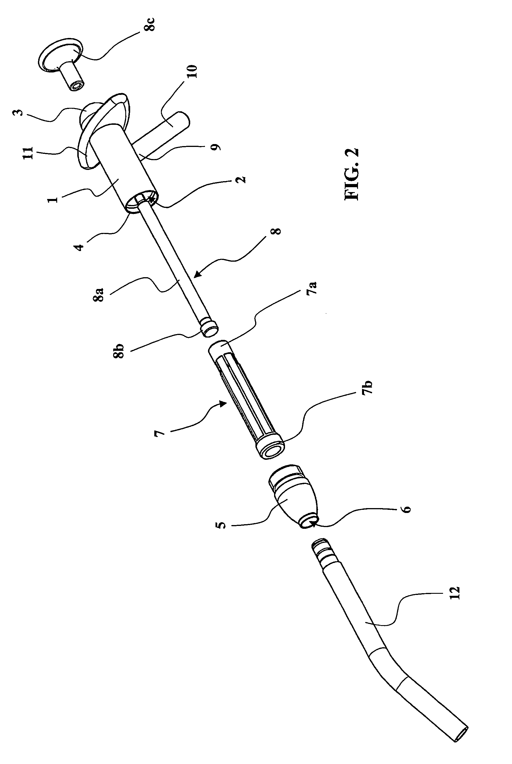
[0037]The embodiment of a bone recovery device of the invention shown in the figures comprises an axial main body 1 having an axial cavity 2 passing through it with a proximal end 3 and a distal end 4.

[0038]A front connector 5 incorporating an axial passage 6 is fixed to the distal end 4 of the main body 1. In practice, the proximal end of the front connector 5 may be screwed into the distal end 4 of the axial main body 1.

[0039]A filter 7, with filtering walls of generally cylindrical tubular shape, may be fitted into the main body 1 and into the front connector 5. The proximal end region 7a and the distal end region 7b of the filter 7 hold it centered and abutted against the axial main body 1 and the front connector 5, respectively. An annular cavity 18 is left free around the filter 7 between the cylindrical filtering wall of the filter 7 and the respective internal lateral faces 1a and 5a of the axial main body 1 and the front connector 5.

[0040]In practice, the axial main body 1 ...


PUM


Abstract

The bone recovery device of the invention comprises an axial main body with an axial cavity passing through it, a front connector incorporating an axial passage and adapted to be fixed to the main body, a filter with a tubular filtering wall adapted to be fitted into the main body, and a scraper piston that slides inside the filter. The scraper piston blocks the end of the filter, and a radial outlet is provided in the axial main body, with an annular cavity left free around the filter between the filter and the axial main body. A canula is inserted into the distal end of the filter. The recovery device may therefore be used to recover bone retained by the filter during aspiration through the canula by the radial outlet, and bone fragments may be extracted by sliding the piston and withdrawing the canula. The recovery device may therefore be used several times without demounting it.

Description

BACKGROUND OF THE INVENTION[0001]In surgery, especially when fitting dental implants, practitioners are often confronted with a requirement for bone material to be used for backfilling. Backfilling ensures good retention of an implant or contributes to the esthetic aspects of the practitioner's work.[0002]In practice, this refers to carrying out bone micrografts.[0003]Self-grafting is recommended to prevent rejection of the graft. To this end, bone is taken from the patient and reimplanted directly during the intervention, with minimum handling.[0004]Practitioners usually attempt to recover as much bone material as possible from the drills and other tools used. This is not always effective, and the volume of bone recovered is not always sufficient.[0005]In some circumstances, if the quantity of bone recovered is insufficient, synthetic bone backfilling materials may be used. Such materials, although developed for this specific purpose, do not guarantee so readily the absence of graf...

Claims


Application Information

Patent Timeline
Patent Type & Authority Patents(United States)
IPC IPC(8): A61F5/00
CPCA61C1/0076A61C17/043A61M1/0056A61C17/08A61M1/79
Inventor GENEVE, ERICBEJEANNIN, JOHANRICHARD, HERVE
Owner ANTHOGYR SAS
Why Eureka
Try Eureka