Attachment structure for electric junction box

a technology for connecting structures and junction boxes, which is applied in the installation of lighting conductors, electrical apparatus casings/cabinets/drawers, and coupling device connections, etc. it can solve the problems of deteriorating recovery workability, damage, and the block itself colliding with the body panel, so as to prevent the effect of breaking

Active Publication Date: 2009-11-24
YAZAKI CORP
View PDF10 Cites 5 Cited by
  • Summary
  • Abstract
  • Description
  • Claims
  • Application Information

AI Technical Summary

Benefits of technology

[0016]In accordance with the configuration described above, since the junction box body is firmly fixed to the vehicle body through the attaching portion, when unexpected external force acts on the junction box body owing to vibration or shock during vehicle running, the junction box body is prevented from coming off from the vehicle body.
[0019]In accordance with the configuration, the planar area of the one attaching portion is reduced so that the value of stress is increased. This is likely to induce rupture.
[0027]In accordance with this configuration, when the electric wire is pulled, the electric wire is prevented from broken before the junction box body is ruptured from the attaching portion.

Problems solved by technology

This increases the man-hour of separately detaching the junction blocks, thus deteriorating recovery workability.
The junction block itself will collide with the body panel and will be damaged.

Method used


Image

  • Attachment structure for electric junction box
  • Attachment structure for electric junction box
  • Attachment structure for electric junction box

Examples


Embodiment Construction

[0037]Now referring to the drawings, an explanation will be given of an embodiment of the present invention.

[0038]FIGS. 1 to 3 show views showing an embodiment of the attaching structure for an electric junction box. In FIGS. 1 to 3, like reference numerals refer to like parts in the conventional electric junction box.

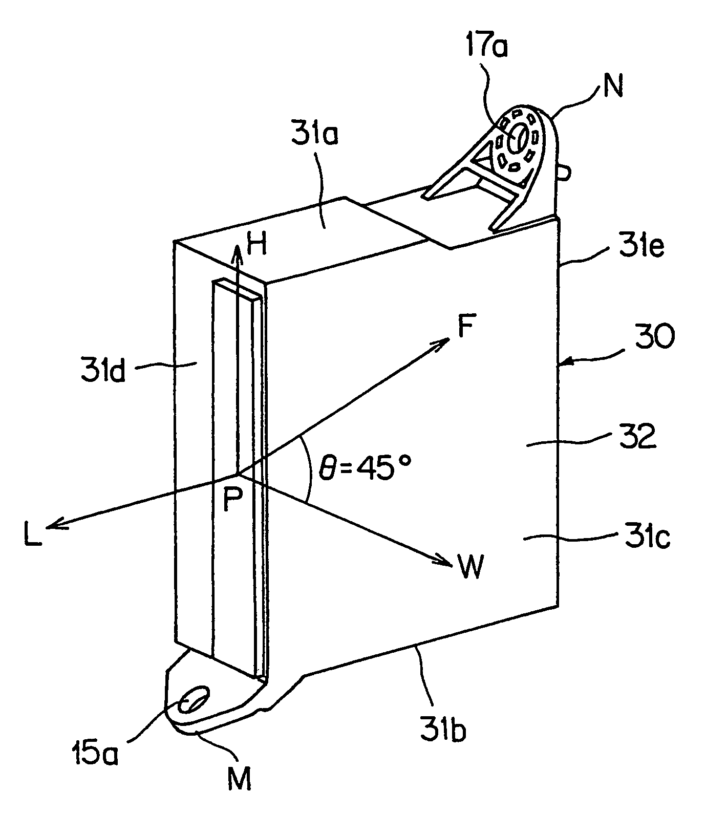
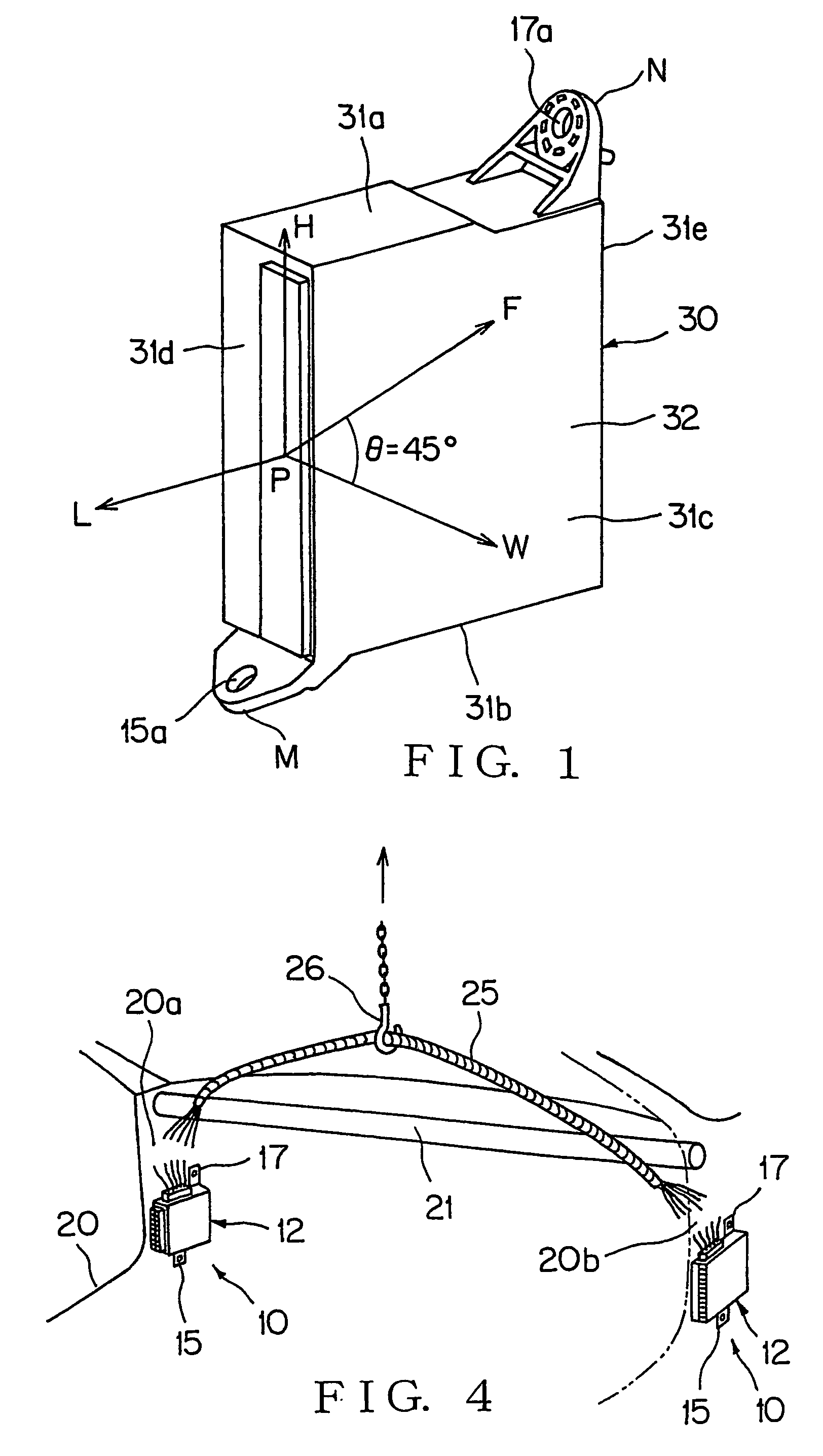
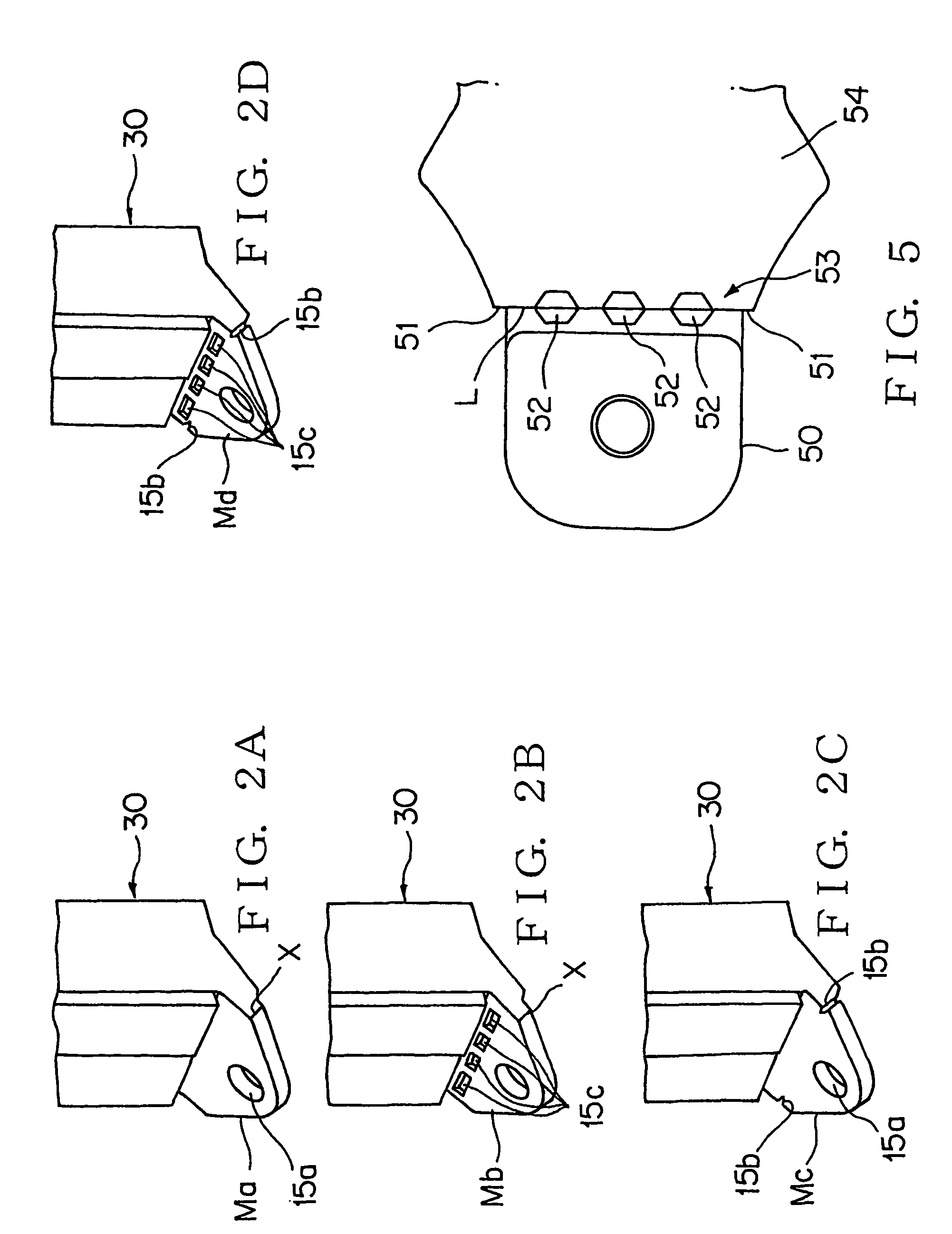
[0039]A junction block 10 which serves as an electric junction box shown in FIG. 3 is a vehicle component which incorporates a branch circuit unit made of a bus bar, an electric wire, etc. and fixed to a body panel (on the side of the vehicle body) 20 of an engine room or passenger room of a vehicle such as a motor vehicle using a tightening member such as a screw.

[0040]The junction block 10 according to the present invention has attaching brackets (attaching portions) 15 and 17 which project on the upper wall 13a and lower wall 13b of a block body (junction box body) 12. The block body 12 is fixed to the body panel 20 through the attaching brackets 15 and 17. The lowe...


PUM


Abstract

A junction block includes attaching brackets projected from the upper wall and lower wall of a block body. The block body is attached to a body panel through the attaching brackets. The attaching bracket to be pulled is provided with a recess 15b and / or a hole 15a for inducing rupture. When a wire harness derived from the block body is pulled in a vehicle width direction during recovery of the junction block, the block body is ruptured-separated from the attaching bracket at the recess 15b and / or hole 15c. In such a configuration, the block body can be rupture-separated only during recovery of a junction box body without being ruptured-separated owing to vibration / shock during vehicle running to improve recovery workability and recycling property.

Description

TECHNICAL FIELD[0001]The present invention relates to an attachment structure for an electric junction box attached to a body panel of a motor vehicle and connected to a wire harness, or an electric junction box useful for recovery of a protector.BACKGROUND ART[0002]A large number of long members, e.g. wire harnesses are arranged within a motor vehicle. These wire harnesses are connected to a junction block, a relay block, a connector block, ECU BOX, a protector, etc. which serve as an electric junction box to be fixed to a body panel. For example, as seen from FIG. 4, a junction block 10 fixed to the one panel side 20a of a body panel 20 by a tightening screw (not shown) and another junction box 10 fixed to the other panel side 20b thereof are connected to each other through a wire harness 25. The wire harness 25 is arranged along a reinforcement member 21.[0003]When the vehicle is subjected to the first dismantling (which is carried out for “recycling” of the components which can ...

Claims


Application Information

Patent Timeline
Patent Type & Authority Patents(United States)
IPC IPC(8): H02G3/08B60R16/02H01R13/73H02G3/38H05K5/02
CPCB60R16/0215H01R13/73
Inventor YAMAMOTO, TATSUYAEGAWA, MASATOSHI
Owner YAZAKI CORP
Why Eureka
Try Eureka