
COL (Chip-On-Lead) multi-chip package

a chip-on-lead and multi-chip technology, applied in the field of chip-on-lead (col) multi-chip packages, can solve the problems of broken wires, inability to balance the upper and lower mold flows, and limited number of chips that can be stacked inside a package, so as to reduce the shifting of leads

Inactive Publication Date: 2009-11-24
POWERTECH TECHNOLOGY
View PDF1 Cites 7 Cited by
  • Summary
  • Abstract
  • Description
  • Claims
  • Application Information

AI Technical Summary

Benefits of technology

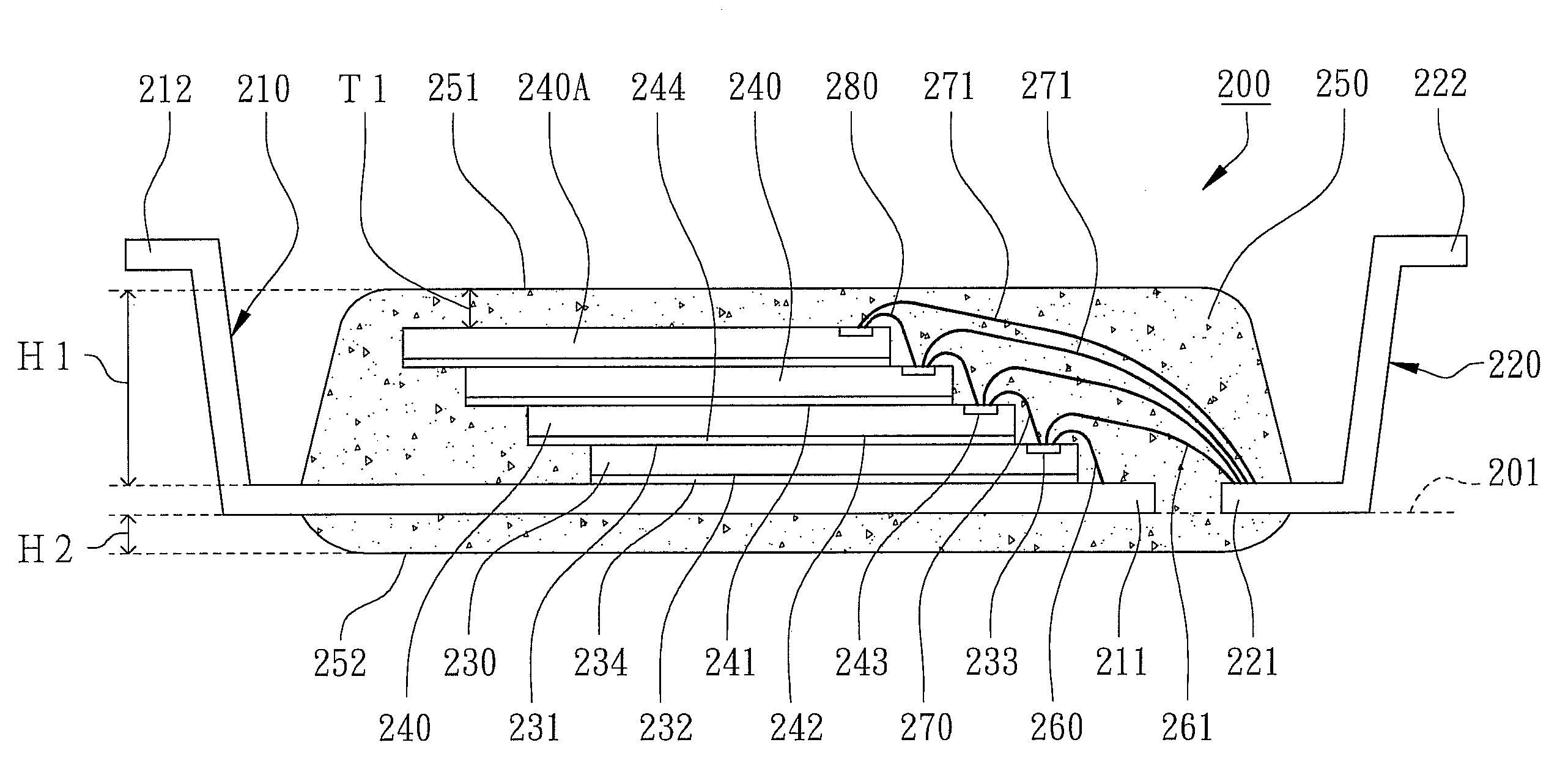
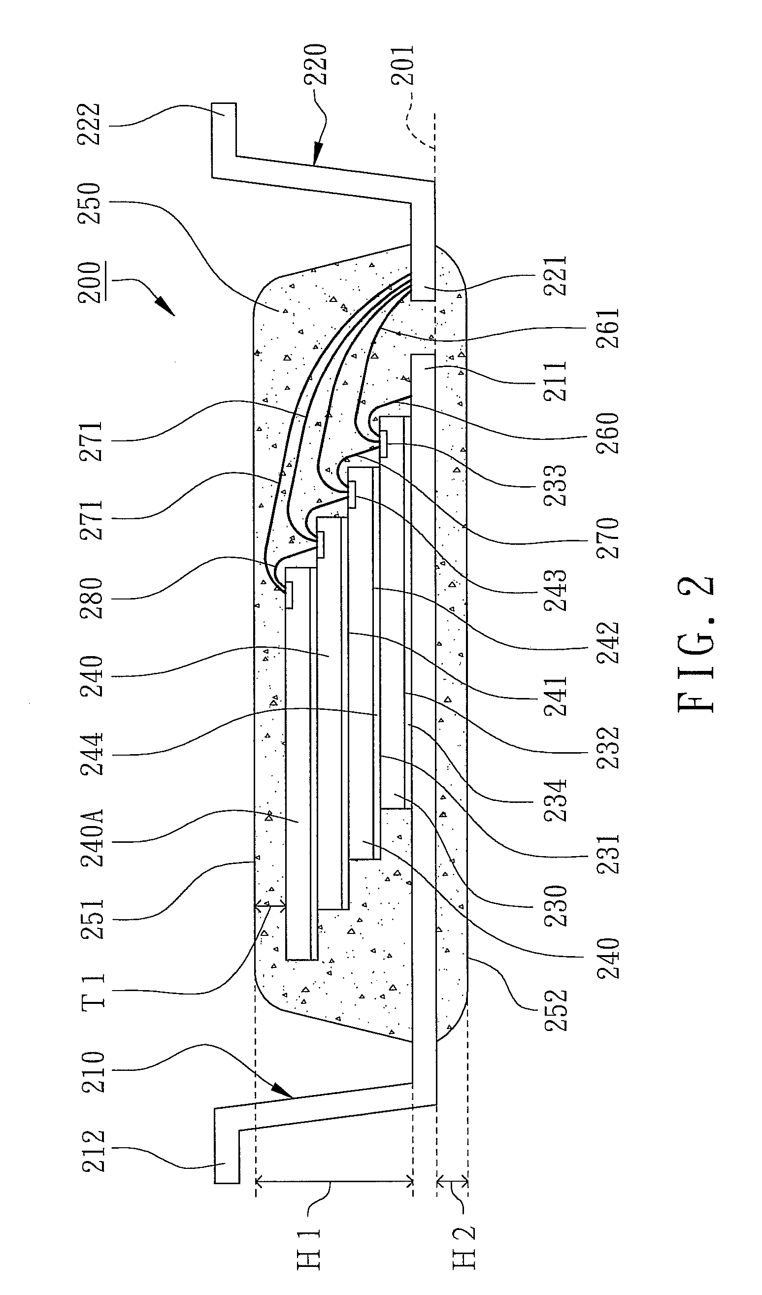
[0004]The main purpose of the present invention is to provide a Chip-On-Lead (COL) multi-chip package without any downset bend of internal leads in an encapsulant to balance the upper and lower mold flows and to reduce the shifting of the leads due to mold flows. Therefore, more chips can be stacked on the leads of the Chip-On-Lead (COL) multi-chip package without any shifting nor tilting.

Problems solved by technology

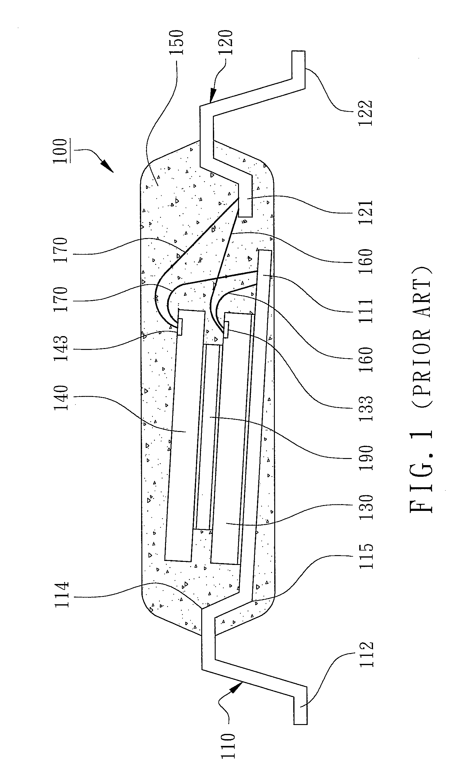
Hence, the number of chips can be stacked inside a package is limited, especially the structural strengths of the leads of COL packages are not strong enough to hold and stack the chips leading to shifting and tilting.
Once the chip position changes, the upper and lower mold flows cannot be balanced.
Furthermore, the mold flow will further pull the first bonding wires 160 and the second bonding wires 170 leading to broken wires, electrical shorts and lower package yield.

Method used


Image

  • COL (Chip-On-Lead) multi-chip package
  • COL (Chip-On-Lead) multi-chip package
  • COL (Chip-On-Lead) multi-chip package

Examples


Embodiment Construction

[0009]Please refer to the attached drawings, the present invention will be described by means of embodiments below.

[0010]According to the preferred embodiment of the present invention, a Chip-On-Lead (COL) multi-chip package is revealed in the cross-sectional view of FIG. 2. The COL multi-chip package 200 primarily comprises a plurality of first leads 210, a first chip 230, one or more second chips 240, and an encapsulant 250.

[0011]Each first lead 210 has a first internal lead 211 and a first external lead 212 where the internal leads 211 are portions of the first leads 210 disposed inside the encapsulant 250 and the external leads 212 disposed outside the encapsulant 250. The first leads 210 are parts of a metal leadframe made of iron, copper, or other metal alloy where the first leads 210 have an appropriate thickness such as 0.125 mm or more with enough structural strengths to support the first chip 230 and the second chips 240. Preferably, the thickness of the first lead 210 can...


PUM


Abstract

A Chip-On-Lead (COL) multi-chip package is revealed, primarily comprising a plurality of leads, a first chip disposed on the first leads, one or more second chips stacked on the first chip, and an encapsulant. The leads have a plurality of internal leads encapsulated inside the encapsulant where the internal leads are fully formed on a downset plane toward and parallel to a bottom surface of the encapsulant. The height between the internal leads to a top surface of the encapsulant is three times or more greater than the height between the internal leads and the bottom surface. Since the number and the thickness of the second chips is under controlled, the thickness between the top surface of the encapsulant and the most adjacent one of the second chips is about the same as the one between the internal leads and the bottom surface of the encapsulant. Therefore, the internal leads of the leads without downset bends in the encapsulant can balance the upper and lower mold flows and carry more chips without shifting nor tilting.

Description

FIELD OF THE INVENTION[0001]The present invention relates to packaged semiconductor devices, especially to Chip-On-Lead (COL) multi-chip packages.BACKGROUND OF THE INVENTION[0002]In the conventional semiconductor packages, leadframes have been widely implemented as chip carriers and as electrical connection media. There are several basic packaging configurations according to the features of the chip carriers such as Chip-On-Lead packages (COL), Lead-On-Chip (LOC) packages, and conventional “chip on die pad” packages where COL packages are to attach the back surfaces of the chips, i.e., the surfaces of the chips without ICs, to certain internal sections of the leads, then the chips and the leads of leadframes are encapsulated by molding. In order to balance the upper and lower mold flows during transfer molding, at least two downset bends are formed on the leads or on the tie bars of the die pad leading to shaking of the leads. Once experienced the pressure of the mold flows during m...

Claims


Application Information

Patent Timeline
Patent Type & Authority Patents(United States)
IPC IPC(8): H01L23/495
CPCH01L23/4951H01L23/49575H01L24/49H01L23/49555H01L2924/01033H01L2224/48091H01L2224/48247H01L2224/49112H01L2224/73265H01L2225/06562H01L2924/01022H01L2924/01029H01L2924/01082H01L2224/48145H01L24/48H01L2224/32145H01L2224/32245H01L2924/00014H01L2924/00H01L2924/00012H01L24/73H01L2924/181H01L2224/45099H01L2224/05599
Inventor FAN, WEN-JENG
Owner POWERTECH TECHNOLOGY
Learn More