Method and device for monitoring radio-frequency exposure in a magnetic resonance measurement

a magnetic resonance measurement and radiofrequency exposure technology, applied in the direction of magnetic measurement, measurement device, instruments, etc., can solve the problems of high patient exposure, -frequency power, and system operation with overly large safety intervals

Inactive Publication Date: 2009-11-24
SIEMENS HEALTHCARE GMBH
View PDF15 Cites 36 Cited by
  • Summary
  • Abstract
  • Description
  • Claims
  • Application Information

AI Technical Summary

Benefits of technology

[0011]An object of the present invention to improve the aforementioned method for monitoring the physiological effective radio-frequency exposure in a magnetic resonance measurement, as well as a corresponding radio-frequency monitoring device, so that, even given the use of radio-frequency antenna structures with a number of individually controllable radio-frequency signal channels, the radiated radio-frequency power exceeding a limit value that is dangerous for the patient / test subject is prevented, and an optimally good convergence to this safe limit value is achieved in order to be able to operate with optimally high transmission power within the safe limit values.
[0015]Since, in the inventive method, not only the power but also amplitudes and phases of the individual radio-frequency signals are acquired, these can be used to take into account the overlap of the fields at the various positions given known antenna structures (i.e. known antenna geometry, position of the connections of the feed lines within the geometry etc.) as well as known shape, structure and position of the examination subject within the examination volume in the determination of the local exposure values. Relatively precise local exposure values can be determined in this manner, such that ultimately the exposure control values based thereon also very precisely reflect the actual exposure. Even given complicated field distributions that are generated by arbitrary activation of the individual radio-frequency signal channels, it can be very precisely established when global exposure limit values and local exposure limit values could be exceeded. Measures can then be opportunely introduced beforehand in order to prevent this. Excessive safety intervals are thereby no longer required, such that measurements can be made with the optimal power within the safe limit values and thus a better image quality can be achieved.
[0029]However, these calculations presently require multiple days per model. It is therefore desirable to implement the calculations of the single field distributions therefore in advance for a number of patient model types, and to store the results in a type of library. For the RF exposure monitoring, the single field distributions (calculated in advance) in which a patient model was used that optimally resembles the real patient can then be selected for implementation of the calculations for a specific patient. With this method, the inventive monitoring can be implemented for a number of patients without burdensome computing effort. Only in individual cases is an elaborate calculation of the single field distributions adapted specifically to the patient necessary in advance, and the recalculations generated for these individual cases can likewise be stored in the library so as to be available again for subsequent similar cases.
[0032]This method serves to monitor the radiation of a specific higher dose over a longer time window and simultaneously to ensure that the entire power allowable within the long time window to be monitored is not radiated at the patient within a short time window (and thus a danger exists for the patient due to the short-term exposure super-elevation).

Problems solved by technology

It must also be considered that a lower image quality ultimately leads to exposures possibly not offering the desired diagnosis possibilities, or even to exposures having to be re-acquired, which in turn leads to a higher exposure of the patient.
Given the use of the aforementioned antenna structures with a number of separately controllable radio-frequency signal channels, however, a problem is that the radio-frequency power that ultimately acts on the examination subject (i.e. the patient or test subject) in most cases does not agree with the sum of the individual powers at the various radio-frequency signal channels, since constructive and destructive overlapping of the electrical fields of the individual radio-frequency signal channels occurs.
As before, such systems must therefore be operated with overly large safety intervals.

Method used


Image

  • Method and device for monitoring radio-frequency exposure in a magnetic resonance measurement
  • Method and device for monitoring radio-frequency exposure in a magnetic resonance measurement
  • Method and device for monitoring radio-frequency exposure in a magnetic resonance measurement

Examples


Embodiment Construction

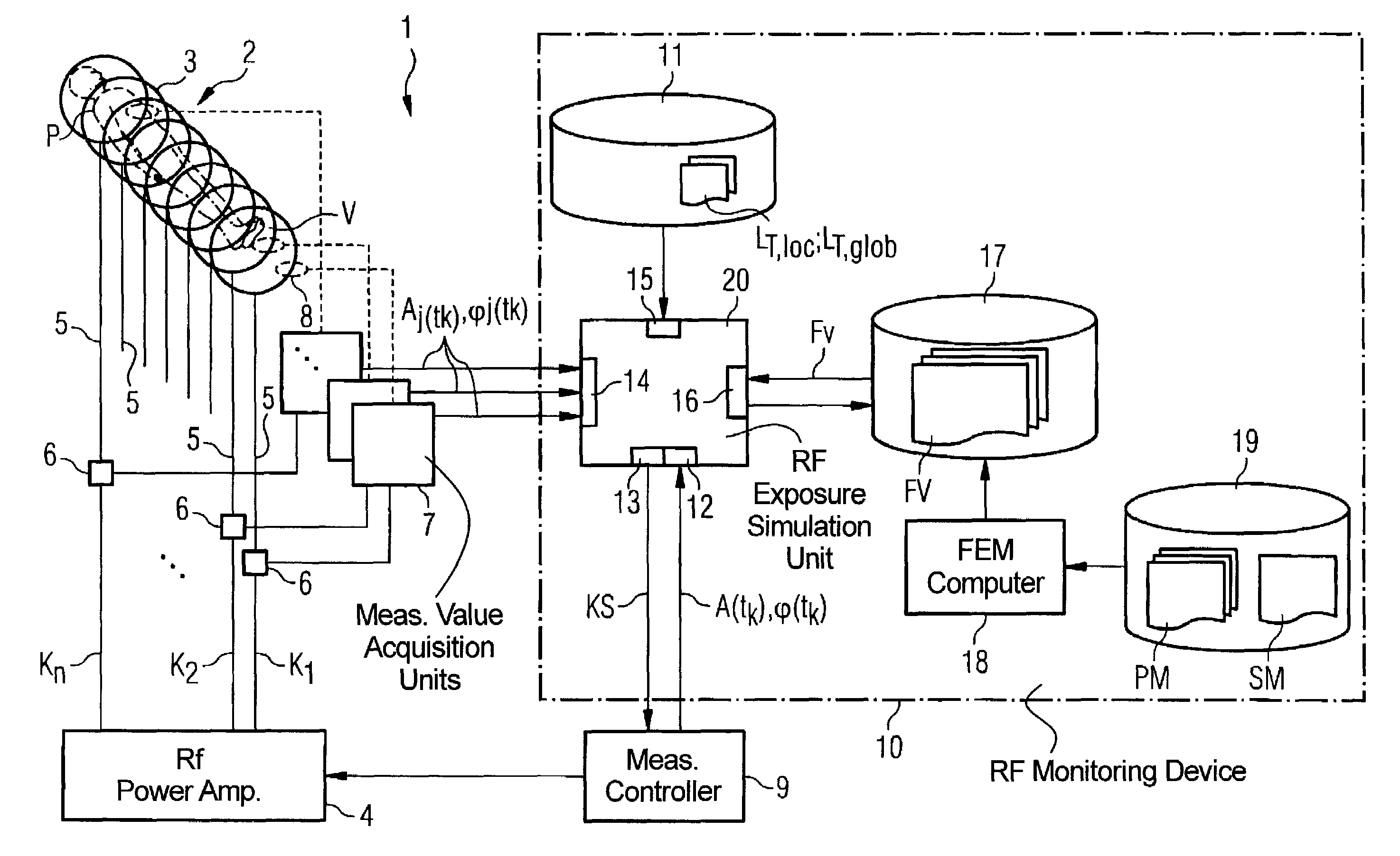
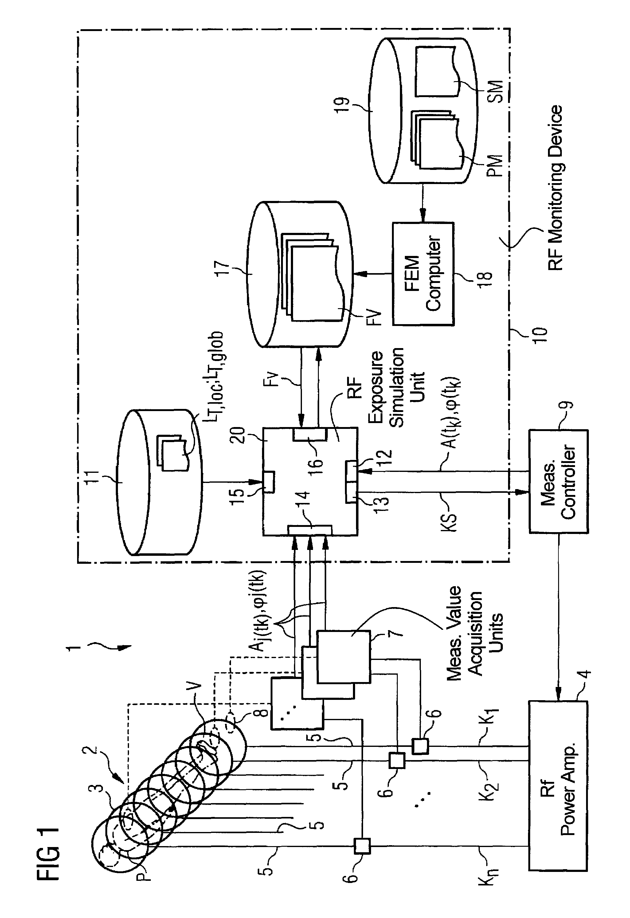
[0036]As an important component of a magnetic resonance system 1, FIG. 1 schematically shows an antenna structure 2 that encloses an examination volume V in which an examination subject P (here a patient P) is located. The antenna structure 2 includes a number of individual antenna elements 3 that are represented in FIG. 1 as individual annular coils, but the antenna structure can be fashioned differently. The antenna elements 3 are respectively connected via separate antenna feed lines 5 (also called feed lines) with a radio-frequency power amplifier 4 that delivers radio-frequency signals in a power range between 10 watts and 20 kW for the antenna elements 3. The individual antenna elements 3, together with their associated antenna feed lines 5, respectively form radio-frequency signal channels K1, K2, . . . , Kn (also called “transmission channels” in the following). Each transmission channel K1, K2, . . . , Kn is separately controlled by the radio-frequency power amplifier 4, me...


PUM


Abstract

In a method and device for monitoring the physiologically effective radio-frequency exposure in at least one specific volume region of an examination subject in a magnetic resonance data acquisition scan in a magnetic resonance system, amplitude values are acquired that respectively represent, at specific acquisition points in time, a signal amplitude of the radio-frequency signals emitted or to be emitted via the radio-frequency signal channels. Also, phase values are acquired that represent the phases of the appertaining radio-frequency signals at these points in time. Local exposure values are then determined on the basis of the amplitude values and phase values, respectively representing a physiological exposure that the radio-frequency pulses cause at the examination subject at a specific location at a specific time. Based on this, exposure control values are determined that are compared with predetermined exposure limit values. When an exposure limit values is reached or exceeded, a control signal is output.

Description

BACKGROUND OF THE INVENTION[0001]1. Field of the Invention[0002]The present invention concerns a method for monitoring the physiologically effective radio-frequency exposure or in at least one specific volume region of an examination subject in a magnetic resonance measurement (i.e., data acquisition sequence or in a magnetic resonance system, the magnetic resonance system having a radio-frequency antenna structure with a number of individually controllable radio-frequency signal channels for generation of radio-frequency distributions in an examination volume including the examination subject. Moreover, the invention concerns a corresponding radio-frequency monitoring device for implementation of such a method as well as a magnetic resonance system with such a radio-frequency monitoring device.[0003]2. Description of the Prior Art[0004]Magnetic resonance tomography has in recent years become established as an imaging modality in the medical field. The method essentially proceeds in...

Claims


Application Information

Patent Timeline
Patent Type & Authority Patents(United States)
IPC IPC(8): G01V3/00
CPCG01R33/5612G01R33/3415G01R33/288
Inventor FONTIUS, JOERG ULRICHNISTLER, JUERGENRENZ, WOLFGANGSCHMITT, FRANZWICKLOW, KARSTEN
Owner SIEMENS HEALTHCARE GMBH
Why Eureka
Try Eureka