Magnetic sensing element having reactive-ion-etching stop layer and process for producing same

a technology of reactive ion etching and magnetic sensing elements, which is applied in the direction of metal sheet cores, magnetic bodies, instruments, etc., can solve the problems that the known process for producing tunneling magnetic sensing elements cannot effectively reduce the distance between shield layers, and cannot be formed at each side of the laminate, so as to achieve the effect of reducing the distance, reducing the distance, and reducing the distan

Active Publication Date: 2009-11-24
TDK CORPARATION
View PDF11 Cites 16 Cited by
  • Summary
  • Abstract
  • Description
  • Claims
  • Application Information

AI Technical Summary

Benefits of technology

[0022]The first RIE stop layer and the second RIE stop layers are preferably composed of the same material. This effectively reduces the variation in the distance between the shield layers. Preferably, the first RIE stop layer and the second RIE stop layers are each composed of at least one element selected from the group consisting of Cr, Pt, Ir, Ru, Rh, Pd, and Ag. This achieves appropriately reduced etch rates of the first and second RIE stop layers in reactive ion etching, thereby more effectively reducing the variation in the distance between the shield layers.
[0039]Preferably, the first RIE stop layer and the second RIE stop layer are each composed of at least one element selected from the group consisting of Cr, Pt, Ir, Ru, Rh, Pd, and Ag. This easily and appropriately achieves lower etch rates of the first and second RIE stop layers in reactive ion etching compared with those of the RIE-controlling layer and the milling stop layer, which is preferable.

Problems solved by technology

However, if the above-described adjustment is performed, the thick hard bias layer 10 and the like cannot be formed at each side of the laminate 7 in the track width direction (X direction) because of a shadow effect of the very thick resist layer 8.
Thus, the known process for producing the tunneling magnetic sensing element was not able to reduce the variation in the distance between the shield layers.
Alternatively, even if the first RIE stop layer is not entirely removed, in other words, even if part of the first RIE stop layer is left, there is a large step height between the top face of the first RIE stop layer and the top face of the second RIE stop layer at the end of the step (g); hence, the variation in the distance between the shield layers cannot be effectively reduced.

Method used


Image

  • Magnetic sensing element having reactive-ion-etching stop layer and process for producing same
  • Magnetic sensing element having reactive-ion-etching stop layer and process for producing same
  • Magnetic sensing element having reactive-ion-etching stop layer and process for producing same

Examples


Embodiment Construction

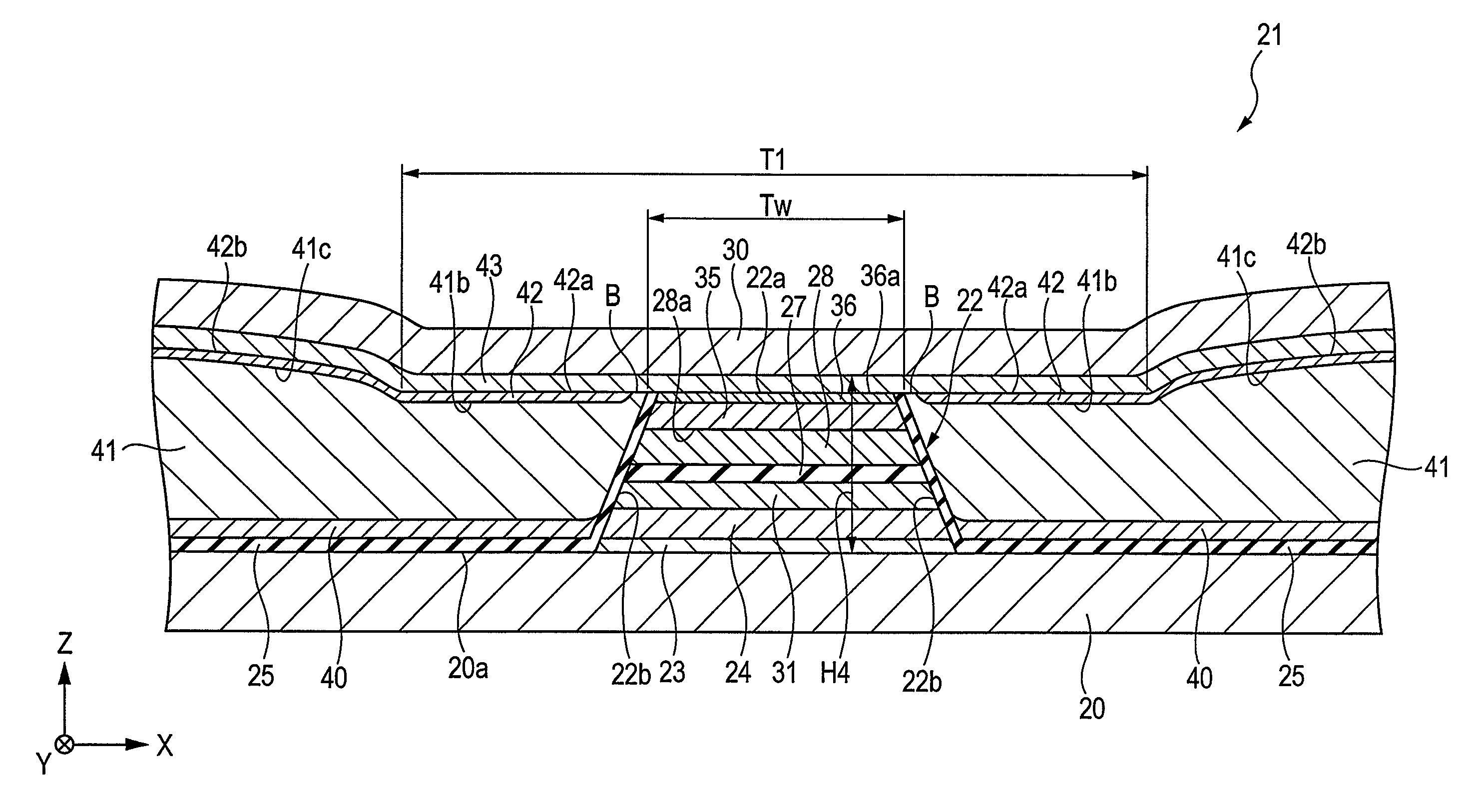
[0056]FIG. 1 is a fragmentary cross-sectional view of a tunneling magnetic sensing element, the view being taken along a plane parallel to a face facing a recording medium.

[0057]A tunneling magnetic sensing element is disposed at a trailing end of a floating slider included in a hard disk system and detects a magnetic field recorded in a hard disk or the like. In FIG. 1, the X direction indicates a track width direction. The Y direction indicates the direction of a magnetic leakage field from a magnetic recording medium (height direction). The Z direction indicates the direction of motion of a magnetic recording medium such as a hard disk and also indicates the stacking direction of layers in the tunneling magnetic sensing element. The X, Y, Z directions are at right angles to one another. The X-Z plane is the plane parallel to the face facing the recording medium.

[0058]A bottom shield layer 20 is composed of a magnetic material such as a NiFe alloy.

[0059]The top face 20a of the bot...


PUM

PropertyMeasurementUnit
angleaaaaaaaaaa
film-forming aaaaaaaaaa
angle θ2aaaaaaaaaa

Abstract

A magnetic sensing element including a laminate and a bias layer is provided. A first reactive-ion-etching (RIE) stop layer is disposed on a free magnetic layer. Second RIE stop layers are disposed on bias layers. The first and second RIE stop layers function as stop layers when layers on the first and second RIE stop layers are removed by reactive ion etching in a production process. Reactive ion etching is completed when the first RIE stop layer and the second RIE stop layers are exposed, the first and second RIE stop layers being disposed at almost the same height. Also provided is a process for producing the magnetic sensing element.

Description

BACKGROUND[0001]1. Field[0002]A magnetic sensing element including a laminate and a bias layer is provided. The magnetic sensing element having a smaller variation in height between the top face of the laminate and top faces of regions where bias layers are disposed. The bias layers are disposed at both sides of the laminate in the track width direction, and the magnetic sensing element has a smaller variation in the distance between shield layers. Also provided is a process for producing the magnetic sensing element.[0003]2. Description of the Related Art[0004]FIGS. 10 to 15 show a process for producing a known tunneling magnetic sensing element. Each of Figures is a cross-sectional view in the production process of the tunneling magnetic sensing element taken along a plane parallel to a face facing a recording medium (the plane parallel to the X-Z plane).[0005]As shown in FIG. 10, a laminate 7 is formed on a bottom shield layer 1, the laminate 7 including, an antiferromagnetic lay...

Claims


Application Information

Patent Timeline
Patent Type & Authority Patents(United States)
IPC IPC(8): G11B5/33G11B5/127
CPCB82Y10/00B82Y25/00B82Y40/00G01R33/093G11B5/3163H01F41/308G11B5/3912G11B5/3932H01F10/3254G11B5/3909G11B2005/3996G11B5/3903G11B5/40
Inventor HONDA, KENJIISHIBASHI, NAOHIROAOKI, DAIGOHAYAKAWA, YASUONISHIYAMA, YOSHIHIROKOBAYASHI, TOSHIHIRO
Owner TDK CORPARATION
Why Eureka
Try Eureka