Integral composite-structure construction system

a composite structure and construction system technology, applied in the direction of structural elements, building components, construction materials, etc., can solve the problems of rebars not working as connectors, bearing concepts cannot be applied, and systems can only be used for small areas

Inactive Publication Date: 2009-12-01
OSPINA PEDRO
View PDF11 Cites 20 Cited by
  • Summary
  • Abstract
  • Description
  • Claims
  • Application Information

AI Technical Summary

Problems solved by technology

“U” shaped holes facilitates the installation of the welded wire fabric from above; these welded wire fabric's transverse rebars take the negative flexural bending of the slab and for this reason the inventor splices them with the rebars of the prefabricated reinforced concrete planks but in no case he considers these transverse rebars, nor could do so, as the beam's horizontal connectors; for this reason this composite system can only be used for small spans and loads because longitudinal shear capacity is limited by the strength due to the sliding friction or bond between the steel of the beam and the concrete, which are numerically similar, and concrete's longitudinal shear strength.
Even though this composite system has holes in its plate-connector, this system does not use rebars as connectors since it uses the welded wire fabric, so the bearing concept on the holes can not he applied because the diameter of the rebars of the wire fabric is much smaller than the holes' diameter.
“U” holes are constructively attractive because they allow to place the wire fabric from above which also makes the shear strength of reinforced concrete to be incremented by the wire fabric rebars' shear strength, but these rebars do not work as connectors.
Finally, none of these patents has a device for leveling the slab or the diaphragm thickness; neither have they fixed the position of the welded wire fabric.

Method used


Image

  • Integral composite-structure construction system
  • Integral composite-structure construction system
  • Integral composite-structure construction system

Examples


Embodiment Construction

[0018]The following description is demonstrative in nature and is not intended to limit the scope of the invention or its application of uses.

[0019]There are a number of significant design features and improvements incorporated within the invention.

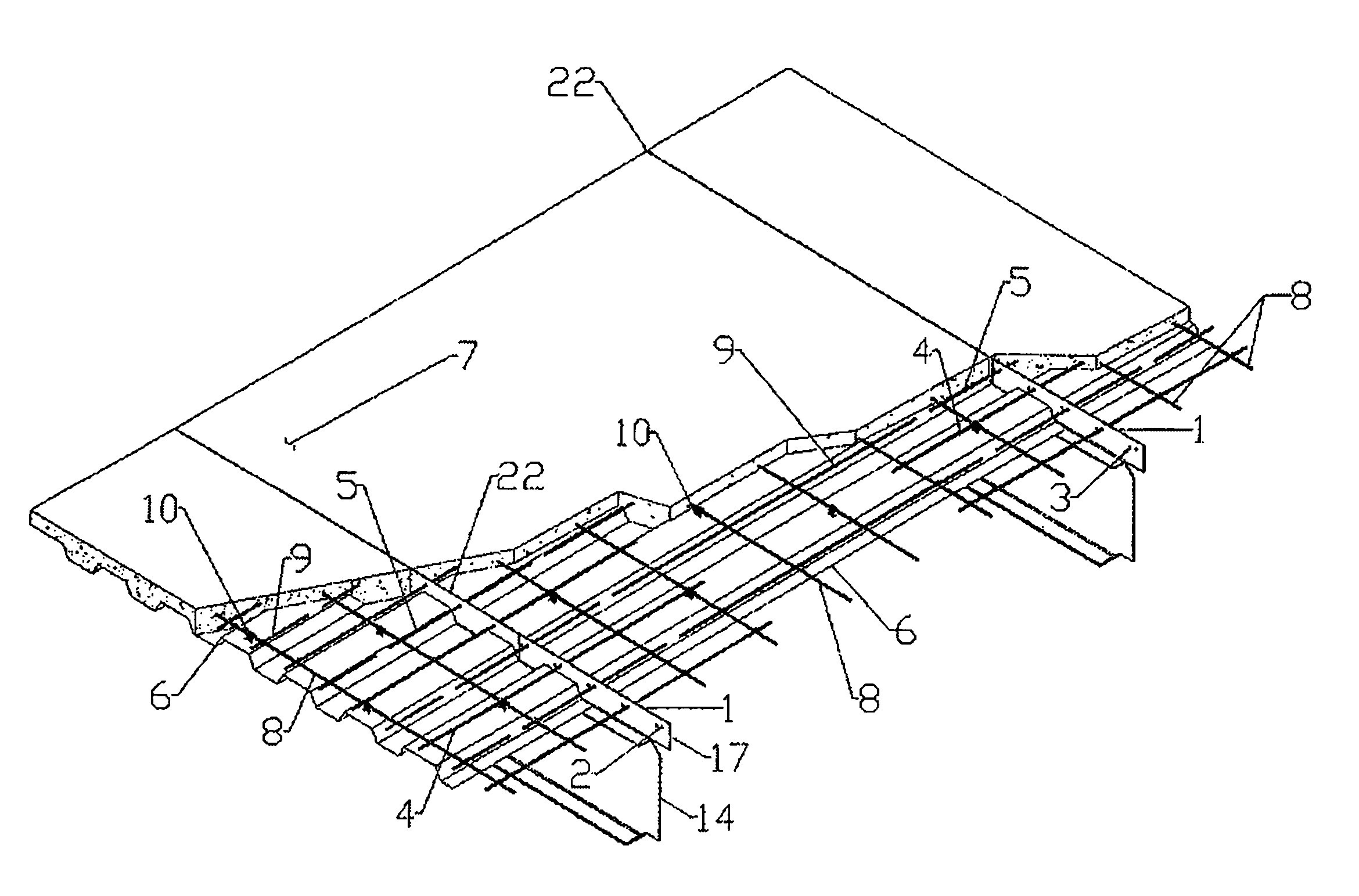
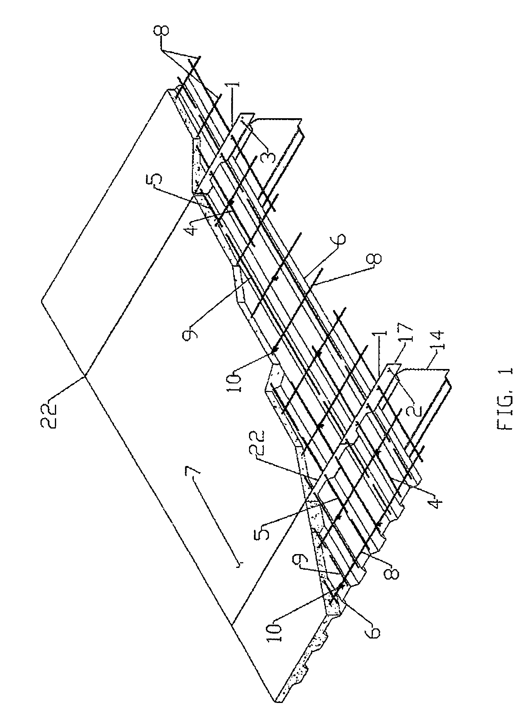
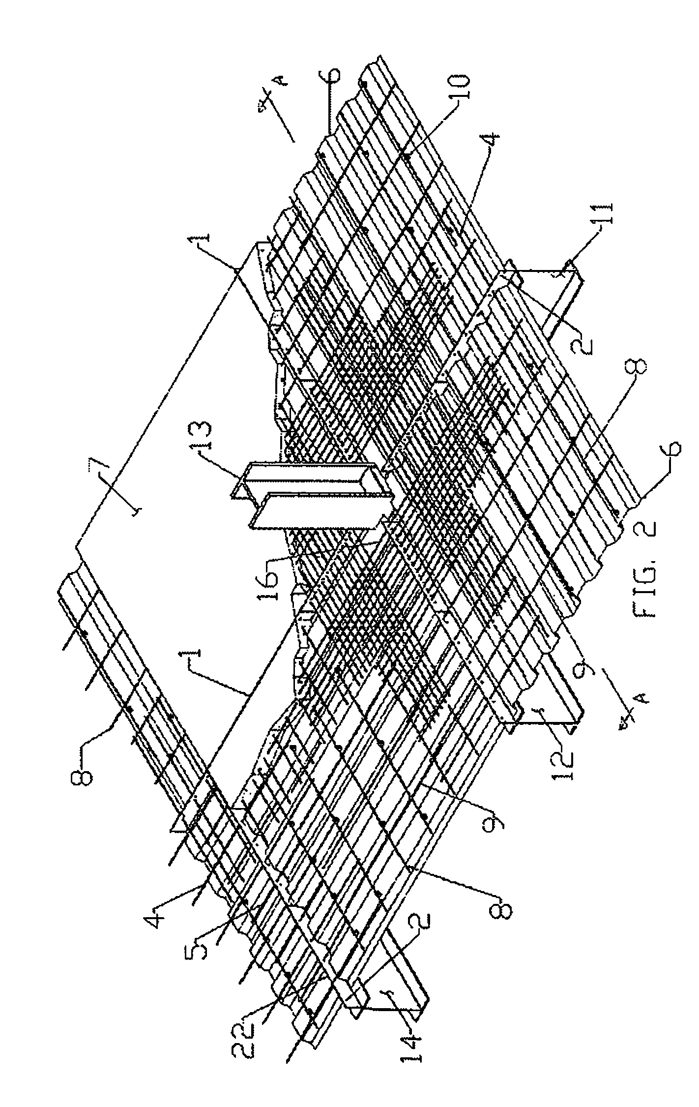
[0020]In simply supported beams (14) the plate-connector (1, 22) with holes (2 and 3) is welded to the top flange of the beam (14) and in combination with the rebars (4 and 5) which go across the holes of the plate-connector it performs the following structural and constructive functions:[0021]The bottom half of the plate-connector (1, 22), in all its length, which equals the span of the beam and on its two faces, takes the compression due to the slab (7) negative flexural bending whose maximum value is located precisely in the vertical plane which coincides with the plane of the plate-connector (1, 22).[0022]The plate-connector (1, 22) takes in all its length and on its two faces, through sliding friction with the slab's concrete, the lo...


PUM

PropertyMeasurementUnit
distanceaaaaaaaaaa
diameteraaaaaaaaaa
hole diametersaaaaaaaaaa

Abstract

Composite structural system for floors or roofs comprising steel beams and reinforced concrete slab or shear walls comprising steel columns and reinforced concrete diaphragms. In both cases a steel plate with holes crossed with rebars is welded to the steel beam or to the steel column which performs the integral combination of the concrete, the structural element and the rebars.

Description

FIELD OF THE INVENTION[0001]This invention significantly increases the efficiency of structural composite systems applied to building construction. The construction of floors or roofs of composite structure for buildings requires the combination, by means of connectors, of steel beams and reinforced concrete slabs; for the construction of shear walls, which have to resist the horizontal forces applied to the composite structure of a building, the system requires to combine steel columns with reinforced concrete diaphragms.DESCRIPTION OF THE PRIOR ART[0002]U.S. Pat. No. 4,592,184 considers a vertical plate connector with protrusions but without holes so the horizontal longitudinal shear of the composite beam is taken only by sliding friction and bond; the welded wire fabric has the objective of controlling the cracks that could appear along the plate-connector but it is not meant to take the slab negative bending nor to work as plate-connector of the composite steel-beam-reinforced-c...

Claims


Application Information

Patent Timeline
Patent Type & Authority Patents(United States)
IPC IPC(8): E04B5/16E04B5/43E04B1/16E04B1/24E04B1/30E04B2/84E04B5/29E04B5/40E04C3/294
CPCE04B1/161E04B1/24E04B1/30E04B5/29E04B5/40E04C3/294E04B5/43E04B2/845E04B2001/2415E04B2001/2445E04B2001/2448E04B2001/2481E04B2001/2484
Inventor OSPINA, PEDRO
Owner OSPINA PEDRO
Why Eureka
Try Eureka