Aircraft with antennas mounted on the tops and bottoms of aerodynamic-surface extensions

a technology of aerodynamic extension and antenna, which is applied in the direction of airflow influencers, fuselages, transportation and packaging, etc., can solve the problems of difficult geometric problems, heavy weight, and inability to maintain a robust uninterrupted communications link between an aircraft in flight and a geosynchronous/geostationary satelli

Inactive Publication Date: 2009-12-01
BEECHCRAFT
View PDF7 Cites 32 Cited by
  • Summary
  • Abstract
  • Description
  • Claims
  • Application Information

AI Technical Summary

Benefits of technology

[0007]The antenna system preferably uses electronically steered antennas, which are light in weight and flat in configuration, rather than the heavier mechanically steerable antennas used in large aircraft such as commercial airliners. Consequently, the present approach is suitable for use in smaller business and personal aircraft, although it may be used with larger aircraft as well to save weight. Phased array antennas allow effective electronic steering of the antenna without physically moving the antenna. Phased array antennas can be made in a flat-panel form that is lighter than the steerable dish antenna taken with its support equipment.
[0011]The first-aerodynamic-surface extension may be of any operable type. In a preferred approach, the first-aerodynamic-surface extension is a winglet. That is, the first-aerodynamic-surface extension may be an up-angled or down-angled aerodynamic surface that not only provides the site for the first-extension top-surface antenna and the first-extension bottom-surface antenna, but also provides improved aerodynamic performance for the aircraft by controlling wing-tip vortices and by other effects. The first-aerodynamic-surface extension may also be a wing-tip pod that provides the site for the first-extension top-surface antenna and the first-extension bottom-surface antenna. The wing-tip pod may optionally provide additional cargo-carrying capacity or fuel-carrying capacity that is needed on some smaller business and personal aircraft. Both winglets and wing-tip pods may have flat panel antennas of the phased-array type made a part of their upper and lower surfaces. Winglets and / or wing-tip pods may be provided in new-make aircraft, but also may be readily added on as aftermarket retrofits to existing aircraft.
[0012]The present approach may be implemented with a single pair of extension antennas that improve the line-of-sight communications-link capability in some flight attitudes. Alternatively and even more preferably, extension antennas are provided for both aerodynamic surfaces of a pair. That is, in the aircraft described above, there is a second aerodynamic surface, such as a wing, joined to the fuselage. The second aerodynamic surface extends generally oppositely to the first aerodynamic surface and has a second distal end remote from the fuselage. The second aerodynamic surface has a second dihedral angle relative to the horizontal plane. A second-aerodynamic-surface extension is joined to the second distal end of the second aerodynamic surface. The second-aerodynamic-surface extension has a second-aerodynamic-surface-extension top surface and a second-aerodynamic-surface-extension bottom surface. The second-aerodynamic-surface-extension top surface lies at a nonzero second-aerodynamic-surface-extension top-surface angle to the horizontal plane that is different from the second dihedral angle, and the second-aerodynamic-surface-extension bottom surface lies at a nonzero second-aerodynamic-surface-extension bottom-surface angle to the horizontal plane that is different from the second dihedral angle. A second-extension top-surface antenna lies in the second-aerodynamic-surface-extension top surface of the second-aerodynamic-surface extension, and a second-extension bottom-surface antenna lies in the second-aerodynamic-surface-extension bottom surface of the second-aerodynamic-surface extension.
[0015]The present approach provides transceiving antennas that are positioned at angles such that at least one of the antennas remains in line-of-sight contact with remote transceiving sites at all times, regardless of the location of the aircraft or its flight attitude. When the aircraft banks, two antennas on the side of the aircraft that dips down are not obscured by the aircraft structure, and at least one of the two antennas remains in line-of-sight communication with the remote site. As long as at least one antenna remains in a line, of sight with the remote site, communications is maintained. The present approach is also compatible with existing antennas mounted to the top, bottom, or sides of the aircraft's fuselage, and with tail-mounted or horizontal-stabilizer-mounted antennas. The use of lightweight flat panel antennas makes practical the use of multiple antennas to maintain the communications links.

Problems solved by technology

Maintaining a robust, uninterrupted communications link between an aircraft in flight and a geosynchronous / geostationary satellite is a challenging geometric problem.
However, steerable dish antennas are too bulky, heavy, and expensive for many smaller aircraft, such as most business and private aircraft.

Method used


Image

  • Aircraft with antennas mounted on the tops and bottoms of aerodynamic-surface extensions
  • Aircraft with antennas mounted on the tops and bottoms of aerodynamic-surface extensions
  • Aircraft with antennas mounted on the tops and bottoms of aerodynamic-surface extensions

Examples


Embodiment Construction

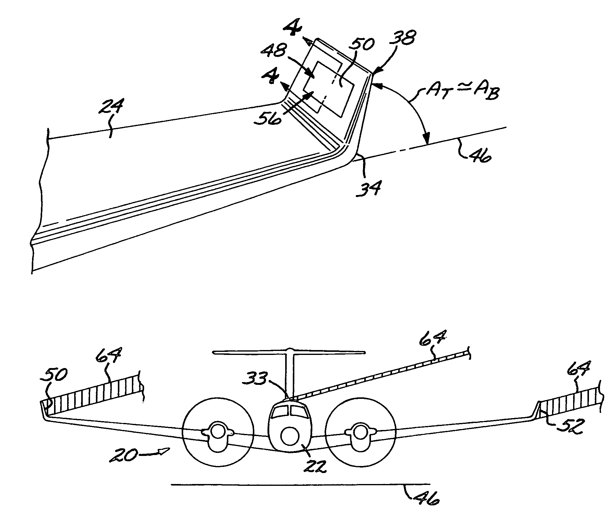
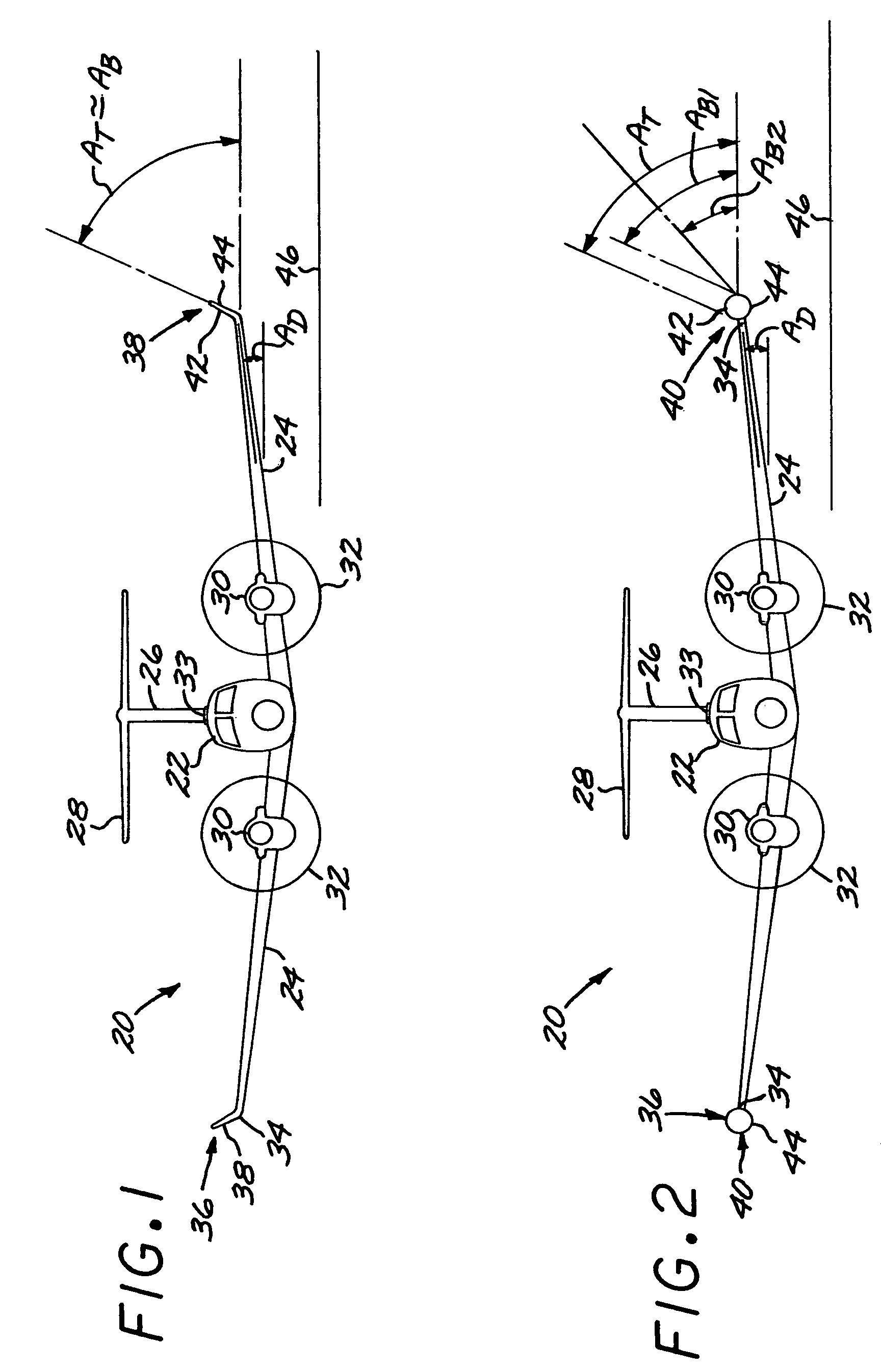
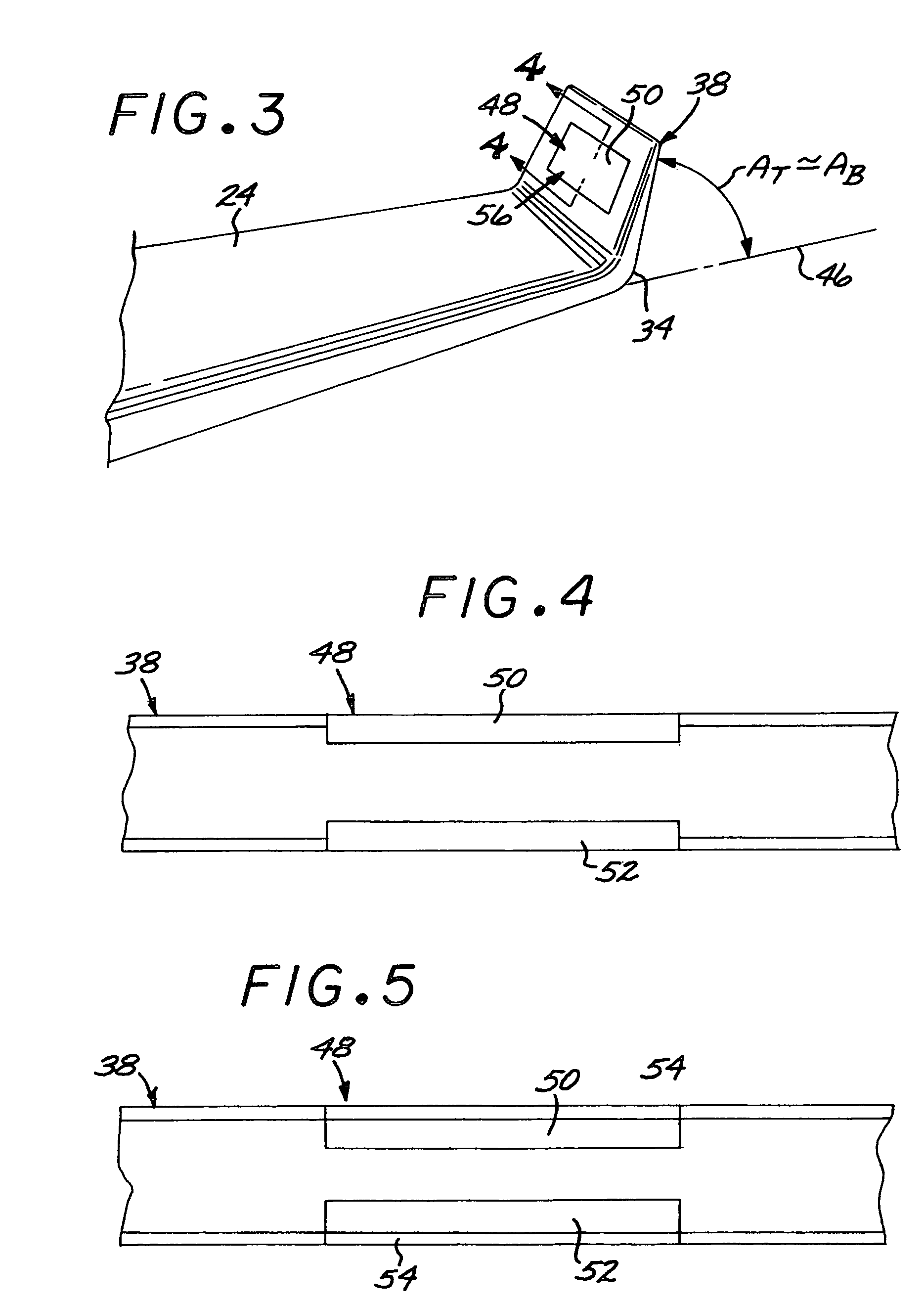
[0038]Preferred embodiments of the approach of the present invention are used in conjunction with an aircraft such as the aircraft 20 illustrated in FIGS. 1-2. The illustrated aircraft 20 has a fuselage 22, at least one wing 24 that serves as an aerodynamic surface joined to the fuselage 22, a vertical tail 26, and horizontal stabilizers 28, which are joined to the vertical tail 26 in the depicted aircraft 20. The wing is oriented at a dihedral angle AD to a horizontal plane 46 when the aircraft 20 is in a level orientation. The horizontal plane 46 is a reference plane that is perpendicular to a radius of the earth passing through the aircraft 20, and thence is generally parallel to the local surface of the earth at the location of the aircraft. The wings of most aircraft have a small positive dihedral angle AD, although aircraft having zero or negative dihedral-angle wings are known.

[0039]As used herein, “fuselage” is broadly defined to be the area of the aircraft, usually lying al...


PUM


Abstract

An aircraft has a fuselage and a pair of wings joined to the fuselage at a dihedral angle. A wing extension, such as an angled winglet or a wing-tip pod, is joined to a distal end of each of the wings. A top-surface antenna lies in each of the top surfaces, and a bottom-surface antenna lies in each of the bottom surfaces. The antennas are preferably flat-panel antennas such as phased-array antennas.

Description

[0001]This invention relates to an aircraft and, in particular, to an aircraft configuration having transceiving antennas positioned on the aircraft to optimize certain types of transmissions.BACKGROUND OF THE INVENTION[0002]Traditionally, aircraft communications have been between ground stations and the aircraft, or between two adjacent aircraft. Ground communications may be interrupted for various reasons, and more recently communications links have been developed between orbiting satellites and aircraft. Transmissions between communications satellites in geostationary or geosynchronous (geostationary / geosynchronous) orbit and aircraft in flight are becoming increasingly important. Transmitted information can include, for example, internet uplinks and downlinks, audio and video entertainment, business information, and information relevant to the aircraft's flight operations such as weather and navigation data.[0003]Maintaining a robust, uninterrupted communications link between an...

Claims


Application Information

Patent Timeline
Patent Type & Authority Patents(United States)
IPC IPC(8): H01Q1/28
CPCB64C1/36H01Q21/061H01Q1/286H04B7/18508
Inventor KRAFT, JOHN R.STEVENS, JASON A.GOFF, JOSHUA T.ROWE, FRANK J.
Owner BEECHCRAFT
Why Eureka
Try Eureka