Supercharge Your Innovation With Domain-Expert AI Agents!

Automatic system clock detection system

a technology of automatic system clock and detection system, which is applied in the direction of generating/distributing signals, pulse techniques, instruments, etc., can solve the problems of increasing complexity of ic, difficulty in supplying accurate, synchronized clocks to the various circuits and logical blocks within the ic, and inability to readily be available or affordable in certain ic designs

Active Publication Date: 2009-12-01
MICROCHIP TECH INC
View PDF15 Cites 0 Cited by
  • Summary
  • Abstract
  • Description
  • Claims
  • Application Information

AI Technical Summary

Benefits of technology

The patent describes a system that helps integrated circuits detect the frequency of an external clock signal and adjust their internal clock accordingly for proper operation. This is done without adding any extra pins or information to the circuit. The system uses an internal ring oscillator and a watchdog counter to compare the input clock with the output clock and determine the clock frequency. This information is then used to set the parameters of the circuit's PLL (phase locked loop) to ensure correct operation. Overall, this system allows for efficient and accurate synchronization of ICs without adding any extra complexity or cost.

Problems solved by technology

As the complexity of ICs increases, so does the difficulty of supplying accurate, synchronized clocks to the various circuits and logical blocks within the IC.
Most IC (or chip) vendors do not have a solution for providing a different clock frequency, thus, IC designers have to retrofit their designs to the single clock source limitation or use different chips.
When a solution is offered, it usually requires additional pins and / or control signals, which may not readily be available or affordable in certain IC designs.
Any error in the pin configurations may result in a PLL failure or malfunction.
In addition, the extra pins also increase IC development costs, raising the overall cost of the IC by more than just the cost of the additional pins to the IC package.

Method used


Image

  • Automatic system clock detection system
  • Automatic system clock detection system
  • Automatic system clock detection system

Examples


Embodiment Construction

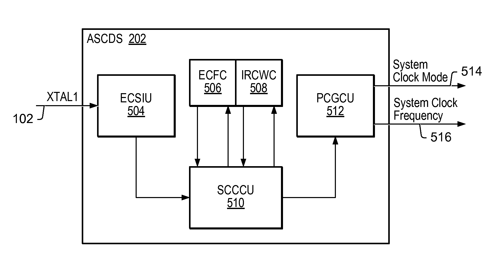
[0020]In one set of embodiments, an integrated circuit may be configured with an Automatic System-Clock Detection System (ASCDS), which may be operable to identify multiple different external periodic signal modes, or external clock source modes. In one embodiment, the ASCDS may be configured to identify two different external periodic signal modes: an external clock oscillator mode, and a crystal (which may be an external crystal) mode. In another set of embodiments, the ASCDS may be operable to identify three or more different external periodic signal modes. In addition, the ASCDS may also be configured to determine the external clock oscillator frequency when the ASCDS is operating in the external clock oscillator mode, prior to engaging an internal phase locked loop (PLL) for generating an internal periodic signal, or clock signal, based on the external periodic signal, or clock signal.

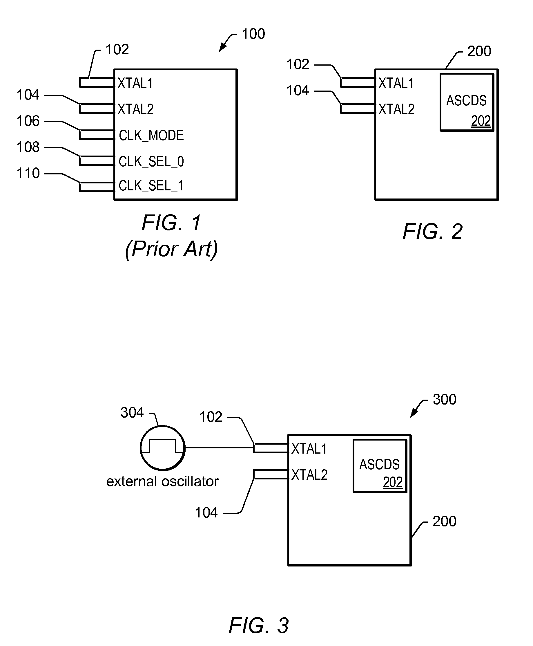
[0021]FIG. 2 shows a block diagram of one embodiment of an integrated circuit (IC) 200 that in...


PUM


Abstract

An Automatic System Clock Detection System (ASCDS) may provide integrated circuits (ICs) with the capability to detect the frequency of an external crystal oscillator or clock source, and adjust the IC's internal PLL accordingly for proper IC operation. The frequency detection and PLL adjustment may be performed without any additional pins on the IC, and / or without requiring any additional external information. The ASCDS may be configured with an internal ring oscillator, which may be generated from standard logic elements, a watchdog counter, and an input clock counter. When the IC comes out of power on reset (POR), the ASCDS may compare the input clock counter with the watchdog counter, and determine the clock frequency of the input clock. It may then set the PLL parameters to ensure correct IC operation.

Description

PRIORITY CLAIM[0001]This application claims benefit of priority of provisional application Ser. No. 60 / 889,431 titled “Automatic System Clock Detection System”, filed on Feb. 12, 2007, whose inventors are Shawn Shaojie Li, Akhlesh Nigam, Mark R. Bohm, and Michael J. Pennell, and which is hereby incorporated by reference as though fully and completely set forth herein.BACKGROUND OF THE INVENTION[0002]1. Field of the Invention[0003]This invention relates to frequency detection circuits, and more specifically to the design of a circuit capable of detecting the frequency of an external clock source and adjust its internal PLL accordingly.[0004]2. Description of the Related Art[0005]In many electronics systems, especially in synchronous digital circuits, a clock signal, oftentimes also referred to as a trigger signal, is used to coordinate the actions of two or more circuits, and / or to predictably trigger system events. A typical clock signal is a square wave oscillating between a high s...

Claims


Application Information

Patent Timeline
Patent Type & Authority Patents(United States)
IPC IPC(8): G06F1/04
CPCH03L7/0995
Inventor LI, SHAWN SHAOJIENIGAM, AKHLESHBOHM, MARK R.PENNELL, MICHAEL J.
Owner MICROCHIP TECH INC
Features
  • R&D
  • Intellectual Property
  • Life Sciences
  • Materials
  • Tech Scout
  • Unparalleled Data Quality
  • Higher Quality Content
  • 60% Fewer Hallucinations
Learn More