
Distortion compensation apparatus

a distortion compensation and apparatus technology, applied in the field of distortion compensation apparatuses, can solve the problems of large scale, low efficiency of front-end distortion compensation scheme, and high cost of feedforward scheme, and achieve the effect of more effective distortion compensation

Inactive Publication Date: 2009-12-01
KOKUSA ELECTRIC CO LTD
View PDF9 Cites 14 Cited by
  • Summary
  • Abstract
  • Description
  • Claims
  • Application Information

AI Technical Summary

Benefits of technology

The present invention provides a distortion compensation apparatus that can effectively compensate for distortion in a signal amplifier. The apparatus includes a nonlinear circuit with an input / output saturation characteristic that generates distortions of odd orders. By using this nonlinear circuit, the apparatus can compensate for distortions of orders other than the target order, resulting in improved compensation for the distortion. The apparatus also includes a distributor, delay line, combiner, and variable phaser to further enhance the compensation. Overall, the apparatus can effectively compensate for distortion in the signal amplifier and improve the quality of the output signal.

Problems solved by technology

The feedforward scheme has a merit that a high amount of distortion compensation can be realized with stable distortion compensation, but also has a demerit that a circuit scale becomes large and the cost of the feedforward scheme becomes higher than that of the front-end distortion compensation scheme with a bad efficiency.
Meanwhile, the analog front-end distortion compensation method has a merit that a circuit scale becomes small with a good economy, but also has a demerit that an amount of distortion compensation becomes lower than the compensation amounts of the other distortion compensation methods.
The digital front-end distortion compensation method has a merit that a high amount of distortion compensation can be realized with a good power efficiency and a good productivity, but also has a demerit that a circuit scale becomes large and the cost becomes higher than that of the analog arrangement.

Method used


Image

  • Distortion compensation apparatus
  • Distortion compensation apparatus
  • Distortion compensation apparatus

Examples


Embodiment Construction

[0055]Embodiments of the present invention will be explained by referring to the accompanied drawings.

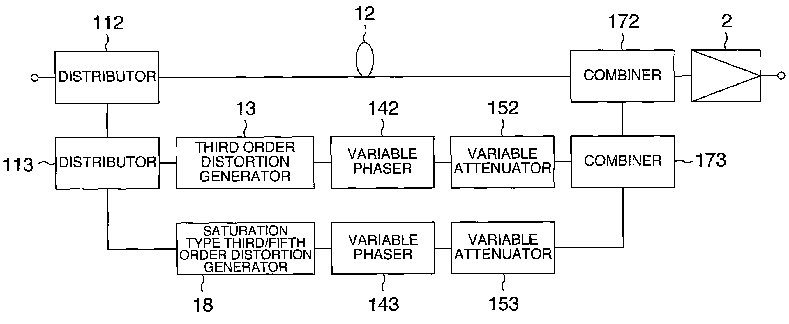
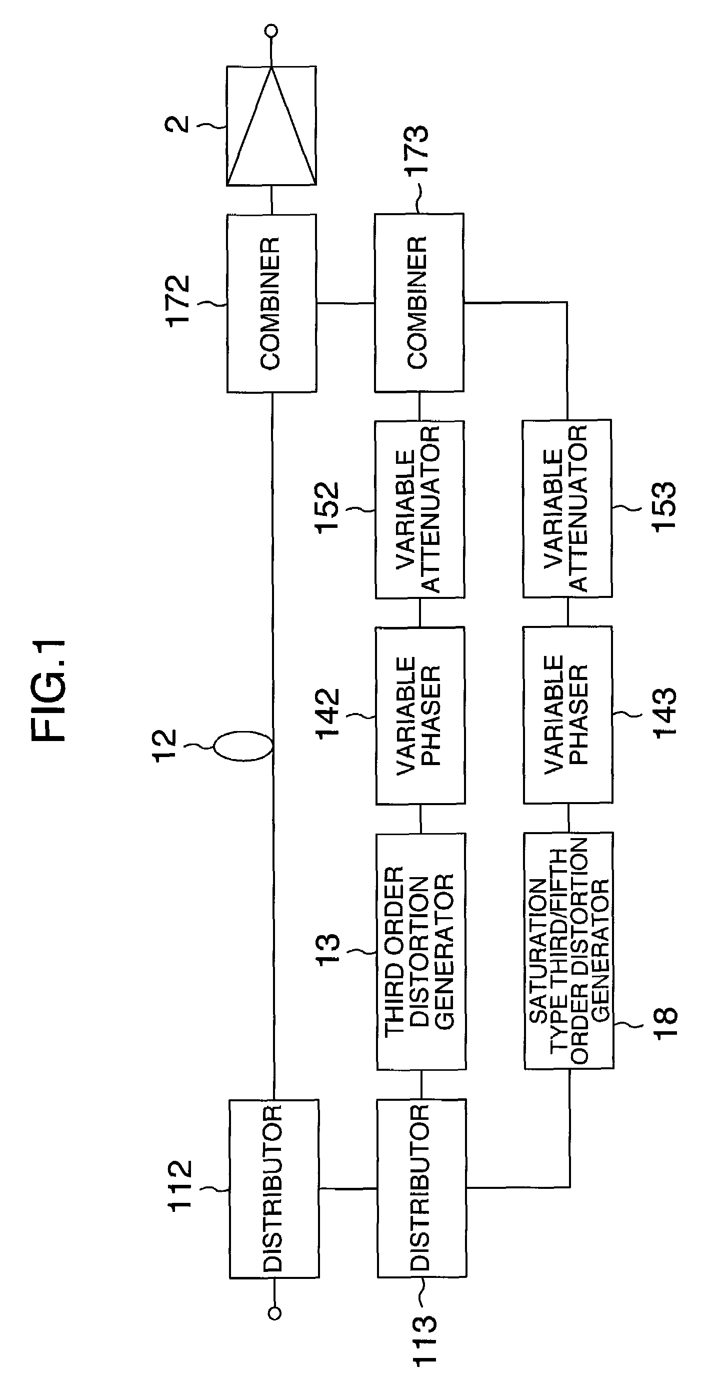
[0056]In the present embodiments, explanation will be made as to the circuit configuration of a distortion compensation apparatus for reducing a distortion generated in an amplifier used in a base station amplification device or a relay unit in a wireless system and also as to its control method. More in particular, explanation will be made as to a distortion compensation apparatus which uses a front-end distortion compensation circuit as a distortion compensation scheme circuit, has a high compensation with an inexpensive circuit configuration, and achieves stable control.

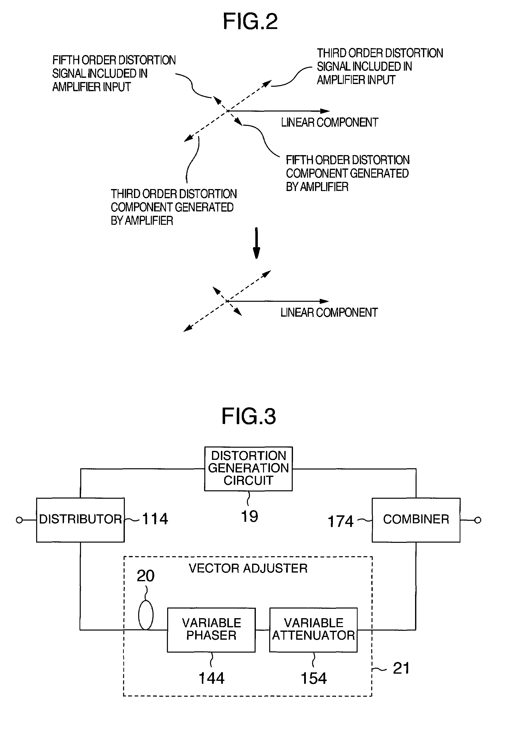
[0057]For the convenience of explanation, similar constituent elements in FIGS. 1, 3, 6, 7, and 9 are denoted by the same reference numerals. The arrangement or configuration of these drawings are illustrated merely as an example, and various sorts of arrangements or configurations may be employed.

[0058]FIG. 1 sho...


PUM


Abstract

A distortion compensation apparatus includes distortion generating means for generating distortions to compensate for a distortion generated in an amplifier 2. The distortion generating means includes a nonlinear circuit 13 having an input / output expansion characteristic as a circuit which generates a distortion of the lowest odd order as a compensation target and also includes a nonlinear circuit 18 having an input / output saturation characteristic as a circuit which generates a distortion of another odd order as a compensation target.

Description

INCORPORATION BY REFERENCE[0001]The present application claims priority from Japanese application JP2007-112732 filed on Apr. 23, 2007, the content of which is hereby incorporated by reference into this application.BACKGROUND OF THE INVENTION[0002]The present invention relates to distortion compensation apparatuses and more particularly, to a distortion compensation apparatus which effectively compensates for a distortion.[0003]As typified by a cellar phone, in these days, such a system as to utilize wireless communication widely spreads. Most of recent wireless systems employ a linear modulation scheme, in which amplification circuits for signals are required to have a linearity feature. As typified by multicarrier amplification, further, signals are amplified at once to reduce a cost and increase an efficiency. In order to satisfy such requirements, an amplification system employing a distortion compensation scheme is generally used, but amplification apparatuses employing various...

Claims


Application Information

Patent Timeline
Patent Type & Authority Patents(United States)
IPC IPC(8): H03F1/26
CPCH03F1/3252
Inventor ITO, TAIZOOKUBO, YOICHIDOSAKA, JUNYANOJIMA, TOSHIO
Owner KOKUSA ELECTRIC CO LTD
Learn More