Wavelength converter and two-dimensional image display device

a two-dimensional image and converter technology, applied in the direction of light demodulation, instrumentation, laser details, etc., can solve the problems of high difficulty in realizing green light sources, difficult realization of semiconductor lasers and the like, and several problems, and achieve the effect of high outpu

Inactive Publication Date: 2009-12-01
PANASONIC CORP
View PDF8 Cites 80 Cited by
  • Summary
  • Abstract
  • Description
  • Claims
  • Application Information

AI Technical Summary

Benefits of technology

[0012]In order to solve the above contradicting problems, an object of the present invention is to provide a wavelength converter capable of stably obtaining W-class high-output green and blue laser beams and a high-luminance 2D image display device using this wavelength converter.
[0014]According to the present invention, there can be obtained a wavelength converter capable of stably obtaining W-class green and blue laser beams having high outputs.
[0016]According to the present invention, there can be obtained a 2D image display device capable of stably obtaining W-class green and blue laser beams having high outputs.

Problems solved by technology

For green and blue light sources, however, realization by semiconductor lasers and the like is difficult and small-size light sources having high productivity are still asked for.
Above all, it is highly difficult to realize green light sources since there is no material suitably usable for semiconductor lasers to obtain green output beams.
However, several problems need to be solved in order to obtain W-class high-output green and blue beams using such a wavelength converter.
However, in a fiber laser light source in which the output of a fundamental wave exceeds 7 W, it has been difficult to efficiently radiate heat generated by a fiber and to improve a conversion efficiency from an excitation light to an emission light.
In the case of using a metallic reel as in the prior art, there have been problems of higher parts cost and production cost and difficult miniaturization.
However, this makes the handling more difficult and requires a larger space, thereby presenting a problem of difficult miniaturization.

Method used


Image

  • Wavelength converter and two-dimensional image display device
  • Wavelength converter and two-dimensional image display device
  • Wavelength converter and two-dimensional image display device

Examples


first embodiment

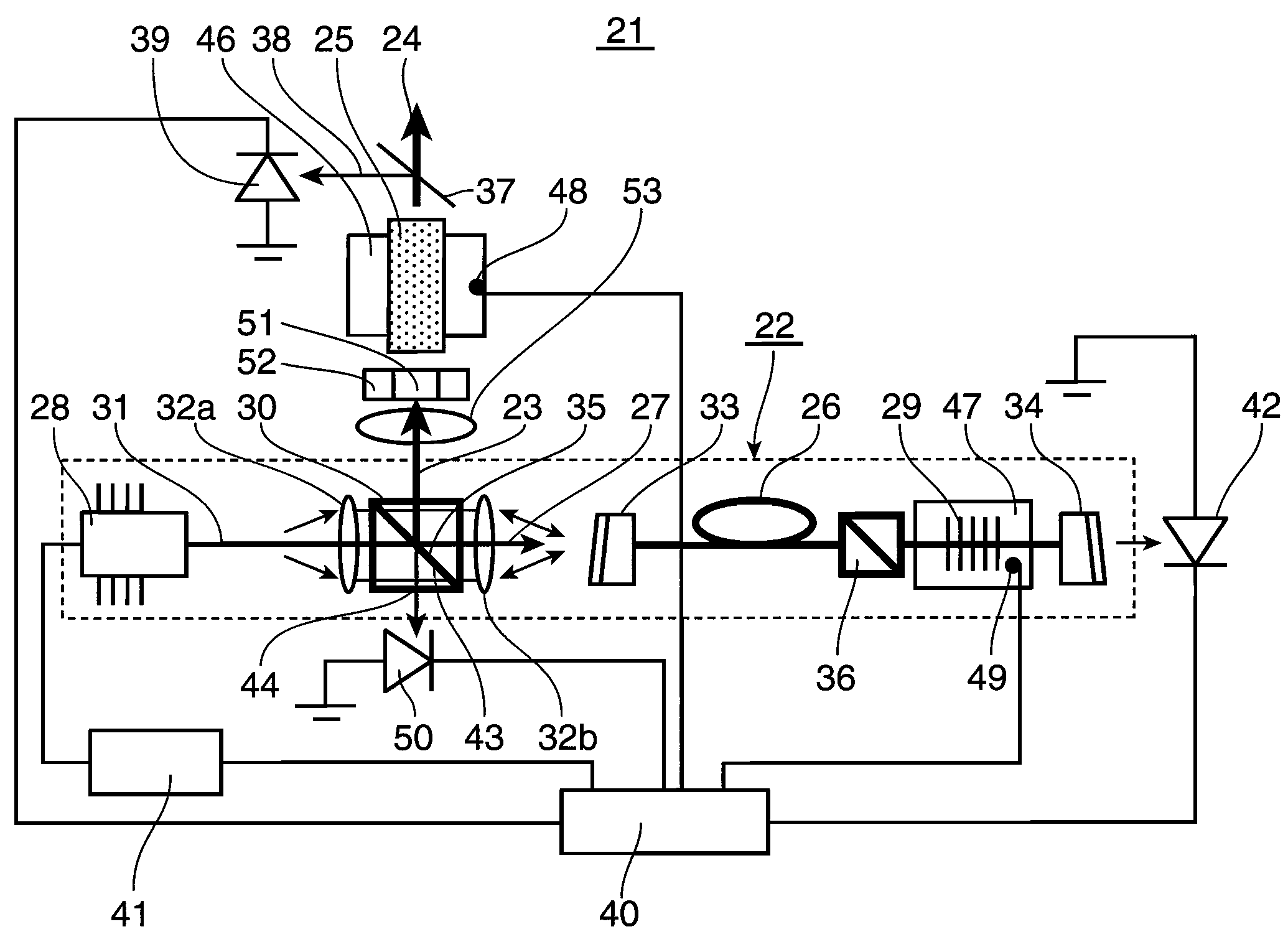
[0035]FIGS. 1 to 5 show a first embodiment of a wavelength converter 21 according to the invention. As shown in FIG. 1, the wavelength converter 21 of this embodiment is provided with a fiber laser 22 and a wavelength conversion element 25 for converting a fundamental wave 23 emitted from the fiber laser 22 into a harmonic output 24.

[0036]The fiber laser 22 includes a fiber 26, a laser light source 28 for outputting an excitation light 27 to be incident on the fiber 26, a fiber grating 29 formed in the fiber 26 for reflecting the fundamental wave having a preselected wavelength and a polarization beam splitter prism 30 for introducing the fundamental wave 23 outputted from the fiber 26 to the wavelength conversion element 25. The polarization beam splitter prism 30 fulfills a function of introducing the excitation light 27 emitted from the laser light source 28 to the fiber 26 by transmitting it and introducing the fundamental wave 23 emitted from the fiber 26 to the wavelength conv...

second embodiment

[0056]FIG. 8 shows a second embodiment of the present invention. A wavelength converter 61 and a fiber laser 62 according to the second embodiment are so constructed as to realize functions similar to those of the first embodiment by another mode. The construction of the second embodiment is successively described with reference to FIG. 8. Structural differences from the first embodiment are that a fiber laser resonator includes a pair of fiber Bragg gratings (FBG 29a, 29b) and that an oscillating laser beam is emitted from an end surface different from an excitation light incident end.

[0057]As shown in FIG. 8, the wavelength converter 61 of this embodiment is provided with the fiber laser 62 and a wavelength conversion element 25 for converting a fundamental wave 23 emitted from the fiber laser 62 into a harmonic output 24.

[0058]The fiber laser 62 includes a fiber 26, a laser light source 28 for emitting an excitation light 27 to be incident on the fiber 26, the FBGs 29a, 29b forme...

third embodiment

[0073]FIG. 12 shows a third embodiment of the present invention. In a wavelength converter 61 of the third embodiment, the polarization beam splitter prism 30 in the construction of the second embodiment is left out. In FIG. 12, a construction similar to the second embodiment is described with the same reference numerals.

[0074]A fiber 26 of the wavelength converter 61 of the third embodiment is doped with Pr (praseodymium) as a rare earth element and adapted to oscillate a red beam having a wavelength of 600 nm (inclusive) to 630 nm (inclusive).

[0075]A fiber laser 62 is provided with an excitation light source 28 including a GaN semiconductor laser (oscillation wavelength of 440 nm (inclusive) to 450 nm (inclusive)), the fiber 26 as a laser medium and fiber gratings 29a, 29b.

[0076]An excitation light emitted from the excitation light source 28 is incident on an end surface 33 of the fiber 26 via lenses 32a, 32b. On the other hand, a fundamental wave 23 is emitted from an end surfac...


PUM

PropertyMeasurementUnit
core diameteraaaaaaaaaa

Abstract

A wavelength converter of the present invention is provided with a laser resonator including a fiber containing an laser-active material and a fiber grating formed in the fiber, a laser light source for emitting an excitation light to the fiber, and a wavelength conversion element for converting a fundamental wave of a laser beam emitted from the laser resonator into a harmonic, wherein the fiber is coiled and has the outer side thereof coated with a heat radiating member having a reflection surface for reflecting light having a wavelength of an excitation light. The wavelength converter is designed to prevent an efficiency reduction caused by the heat generation of a rare-earth doped fiber in a wavelength converter.

Description

BACKGROUND OF THE INVENTION[0001]1. Field of the Invention[0002]The present invention relates to a wavelength converter capable of obtaining a stable high output visible light laser beam by combining a fiber laser and a wavelength conversion element, and a two-dimensional (2D) image display device using this wavelength converter as a light source.[0003]2. Description of the Background Art[0004]A visible light source capable of emitting a highly monochromatic W-class high output is being required to realize large-size displays, high-luminance displays, etc. High-output red semiconductor lasers used in DVD recorders and the like can be utilized as small-size light sources having high productivity for red light out of three primary colors of red, green and blue. For green and blue light sources, however, realization by semiconductor lasers and the like is difficult and small-size light sources having high productivity are still asked for. Above all, it is highly difficult to realize gr...

Claims


Application Information

Patent Timeline
Patent Type & Authority Patents(United States)
IPC IPC(8): G02F1/35G02F2/02H01S3/30
CPCH01S3/042H01S3/06704H01S3/0675G02F1/37H01S3/0405H01S3/094015H01S3/09415H01S3/1305H01S3/1306
Inventor FURUYA, HIROYUKIMIZUUCHI, KIMINORIYAMAMOTO, KAZUHISA
Owner PANASONIC CORP
Why Eureka
Try Eureka