
Method for computing patient radiation dose in computed tomography

a computed tomography and patient technology, applied in material analysis using wave/particle radiation, instruments, nuclear engineering, etc., can solve the problems of not and cannot address ct dosimetry techniques, current scanner technology, and current ct dosimetry standards that typically underestimate the radiation dose to the patien

Active Publication Date: 2009-12-01
RGT UNIV OF CALIFORNIA
View PDF7 Cites 23 Cited by
  • Summary
  • Abstract
  • Description
  • Claims
  • Application Information

AI Technical Summary

Problems solved by technology

Modern CT scanners have modes of operation which current CT dosimetry techniques do not and cannot address.
In addition to the inability to handle current scanner technology for accurate dosimetry, current CT dosimetry standards typically underestimate the radiation dose to the patient for a number of reasons.
The thicker, denser dosimetry phantoms lead to an underestimate of the central radiation doses associated with most body CT procedures.
Unfortunately, at the high energies used in x-ray CT, the scattered radiation propagates to distances in the z dimension of the phantom farther than what the 100 mm pencil chamber can measure.
This geometry therefore leads to an underestimate of the radiation dose due to CT.
These techniques are not practical for routine patient dosimetry, due to the time that they require, and the fact that measurement devices need to be placed internal to the subject being scanned—not feasible for live human imaging.
There are number of developments in CT technology which suggest that a homogeneous PMMA cylinder is no longer adequate (it never was accurate) for patient dosimetry.
Thus, without knowing the patient's shape, accurate dosimetry would be virtually impossible.

Method used


Image

  • Method for computing patient radiation dose in computed tomography
  • Method for computing patient radiation dose in computed tomography
  • Method for computing patient radiation dose in computed tomography

Examples


Embodiment Construction

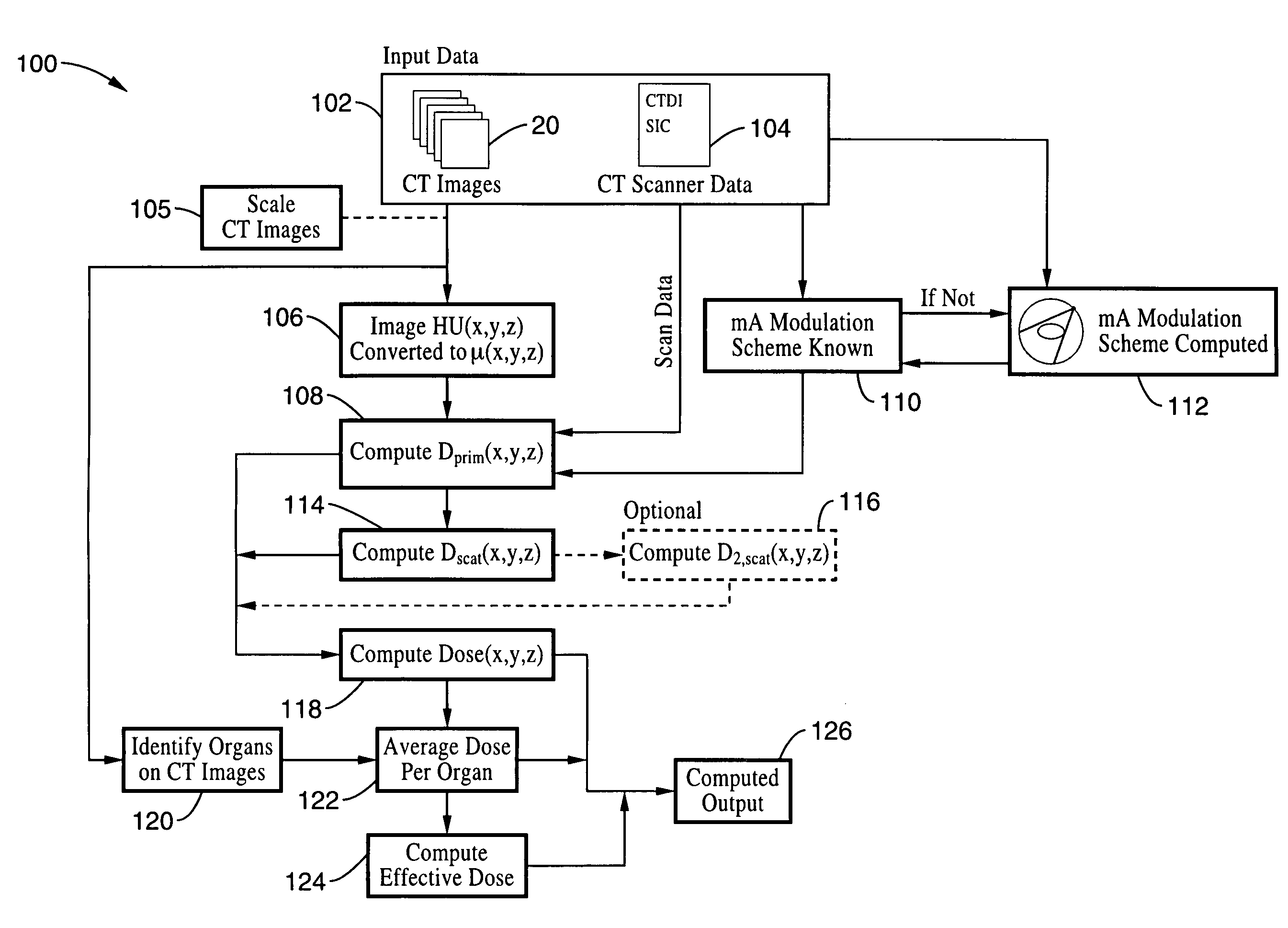
[0077]Referring more specifically to the drawings, for illustrative purposes the present invention is embodied in the apparatus generally shown in FIG. 7 through FIG. 13. It will be appreciated that the apparatus may vary as to configuration and as to details of the parts, and that the method may vary as to the specific steps and sequence, without departing from the basic concepts as disclosed herein.

[0078]FIG. 7 illustrates the geometry for the image based CT dose calculation. The outer circle 50 is the path of the x-ray source 12 around the patient 16 (radius=source 12 to isocenter 52 distance, SIC), and locations P1 and Pk are indicated but there is a complete circular output. The gray block 58 intercepting the x-ray beam 56 represents a bow tie filter. The primary radiation dose to the patient at a location (x,y,z) is indicated at location Dprim(x,y,z).

[0079]The image data set in CT is related to the linear attenuation coefficient (LAC), and it is also an accurate geometrical de...


PUM

PropertyMeasurementUnit
diameteraaaaaaaaaa
sizeaaaaaaaaaa
computed tomographyaaaaaaaaaa

Abstract

A system and method are disclosed for computing a radiation dose delivered to a patient during a computed tomography (CT) scan of the patient. The CT image dataset generated during the scan of the patient, and one or more parameters relating to a x-ray source are used to calculate the radiation dose delivered to the patient as a function of the CT image data set and the one or more parameters of the x-ray source. The radiation dose is generally found by calculating a primary x-ray dose distribution and scattered x-ray dose distribution from the CT image dataset and taking the sum of the primary x-ray dose distribution and scattered x-ray dose distribution.

Description

CROSS-REFERENCE TO RELATED APPLICATIONS[0001]This application claims priority from, and is a 35 U.S.C. § 111(a) continuation of, co-pending PCT international application serial number PCT / US2006 / 045303, filed on Nov. 21, 2006, incorporated herein by reference in its entirety, which claims priority from U.S. provisional application Ser. No. 60 / 738,704, filed on Nov. 21, 2005, incorporated herein by reference in its entirety.STATEMENT REGARDING FEDERALLY SPONSORED RESEARCH OR DEVELOPMENT[0002]Not ApplicableINCORPORATION-BY-REFERENCE OF MATERIAL SUBMITTED ON A COMPACT DISC[0003]Not ApplicableNOTICE OF MATERIAL SUBJECT TO COPYRIGHT PROTECTION[0004]A portion of the material in this patent document is subject to copyright protection under the copyright laws of the United States and of other countries. The owner of the copyright rights has no objection to the facsimile reproduction by anyone of the patent document or the patent disclosure, as it appears in the United States Patent and Trad...

Claims


Application Information

Patent Timeline
Patent Type & Authority Patents(United States)
IPC IPC(8): G01N23/00
CPCG01T1/2985G01T1/02Y10S378/901
Inventor BOONE, JOHN M.
Owner RGT UNIV OF CALIFORNIA
Learn More