Process device with vibration based diagnostics

a process device and vibration-based technology, applied in the field of equipment diagnostics, can solve problems such as vibration from various sources, damage to piping, instruments, and other components of industrial plants, and degradation of components' performan

Inactive Publication Date: 2009-12-01
ROSEMOUNT INC
View PDF473 Cites 30 Cited by
  • Summary
  • Abstract
  • Description
  • Claims
  • Application Information

AI Technical Summary

Problems solved by technology

Vibration of process equipment such as process piping is disruptive to industrial processes and can result in damage to the piping, instrumentation, and other components of the industrial plant.
For example, during normal operation of the process, vibration arises through various sources.
Over extended time, these vibrations can cause degradation in the performance of the components and eventual failure of the components.

Method used


Image

  • Process device with vibration based diagnostics
  • Process device with vibration based diagnostics
  • Process device with vibration based diagnostics

Examples


Embodiment Construction

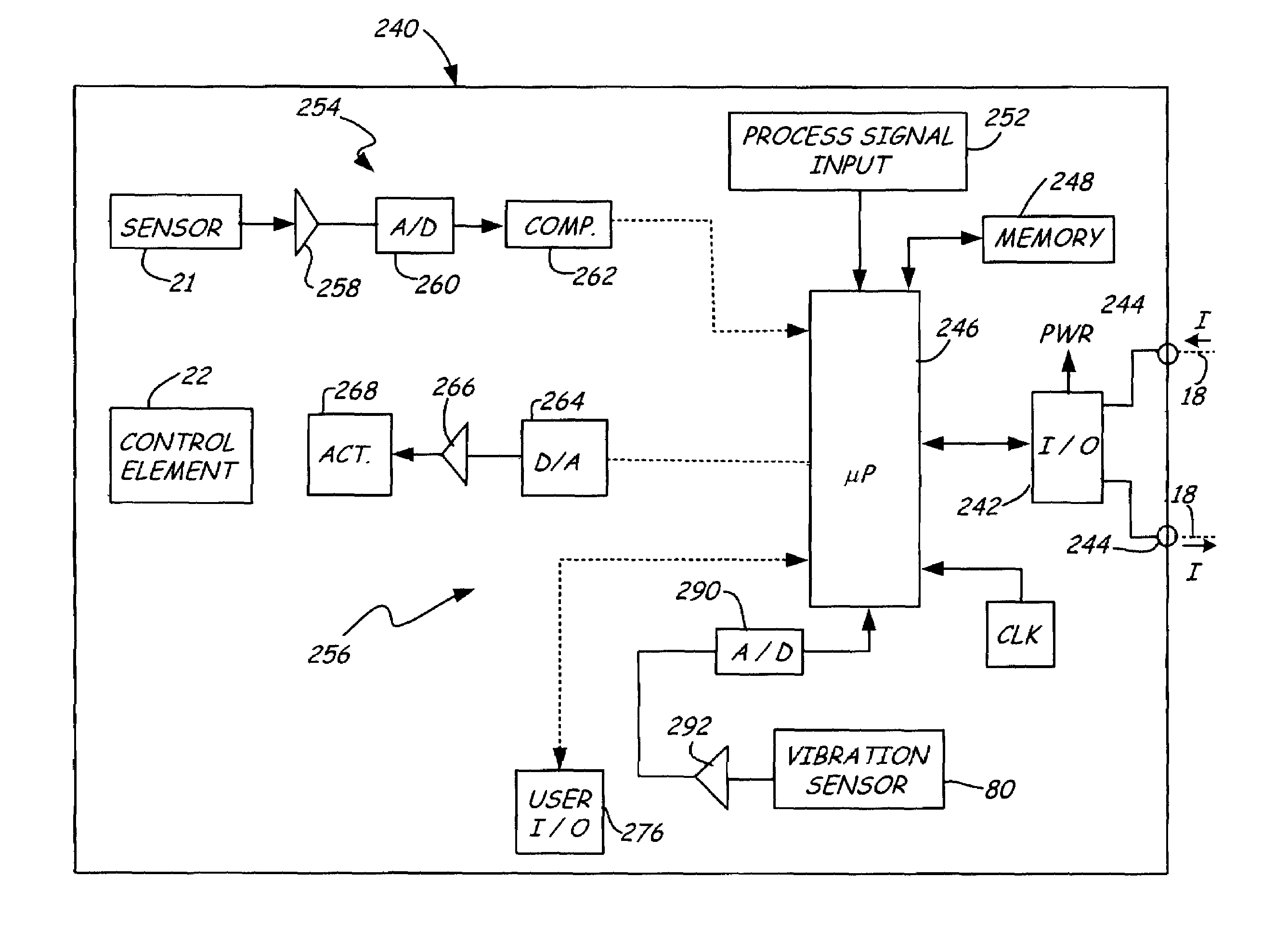
[0010]The present invention provides a diagnostic technique for detecting a failure or predicting a failure or reduction in performance of a process device or a process component prior to the occurrence of the failure or reduced performance. With the present invention, vibrations in the process and / or process device are monitored. Vibrations are detected and used to predict a failure, an impending failure, or reduced performance of the process device or process component.

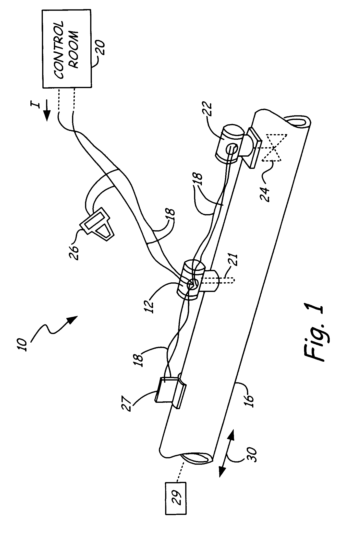
[0011]FIG. 1 is a diagram of process control system 10 which includes a transmitter 12 connected to process pipe 16. As discussed below, transmitter 12 is one type of process device and the present invention is applicable to any process device. Transmitter 12 is coupled to a two-wire process control loop 18 which operates in accordance with the Fieldbus, Profibus or HART® standard. However, the invention is not limited to these standards or a two-wire configuration. Two-wire process control loop 18 runs between tran...


PUM


Abstract

An process device for use in an industrial process control or monitoring system is configured to couple to a process. A vibration sensor is configured to sense vibrations. Diagnostic circuitry provides a diagnostic output based upon the sensed vibrations.

Description

BACKGROUND OF THE INVENTION[0001]The present invention relates to diagnostics of equipment used with industrial processes. More specifically, the invention relates to process devices which perform diagnostics.[0002]Process devices are used in industrial process control systems to control, measure or monitor a process. A control device is a process device which is used to control the process and includes pumps, valves, actuators, solenoids, motors, mixers, agitators, breaker, crusher, roller, mill, ball mill, kneader, blender, filter, cyclone, centrifuge, tower, dryer, conveyor, separator, elevator, hoist, heater, cooler or others. A valve controller includes a valve actuator coupled to a valve used to control flow of process fluid. A pump controller includes a motor controller or actuator coupled to a pump. Other process devices include transmitters which may measure physical parameters such as pressure, temperature, flow, etc. Diagnostics of process devices can be used to identify ...

Claims


Application Information

Patent Timeline
Patent Type & Authority Patents(United States)
IPC IPC(8): G05B13/00G01F1/84G05B23/02
CPCG05B23/027
Inventor LONGSDORF, RANDY J.BLUMEYER, CHAD C.
Owner ROSEMOUNT INC
Why Eureka
Try Eureka