Acoustic pulse flow meter

a flow meter and acoustic technology, applied in the direction of volume/mass flow measurement, measurement devices, instruments, etc., can solve the problems of single pulse and low electrical conductivity of liquids, and achieve the effect of overcoming impedance mismatch and high acoustic power of spark sources

Inactive Publication Date: 2009-12-08
ONICON INC
View PDF4 Cites 44 Cited by
  • Summary
  • Abstract
  • Description
  • Claims
  • Application Information

AI Technical Summary

Benefits of technology

[0012]Piezoelectric receiving transducers are employed in another embodiment of the invention in which a combination of acoustic concentrating structures adjacent the source and receiving transducers, and the high acoustic power of the spark source are adequate to overcome the impedance mismatch between a ceramic element and a flowing gas.

Problems solved by technology

This may also happen with liquids having low electrical conductivity.
However, due to pulse generation difficulties, only a single pulse is normally produced, as compared to the extended bursts of pulses characteristic of prior art ultrasonic flow meters using piezoelectric drive transducers.

Method used


Image

  • Acoustic pulse flow meter
  • Acoustic pulse flow meter
  • Acoustic pulse flow meter

Examples


Embodiment Construction

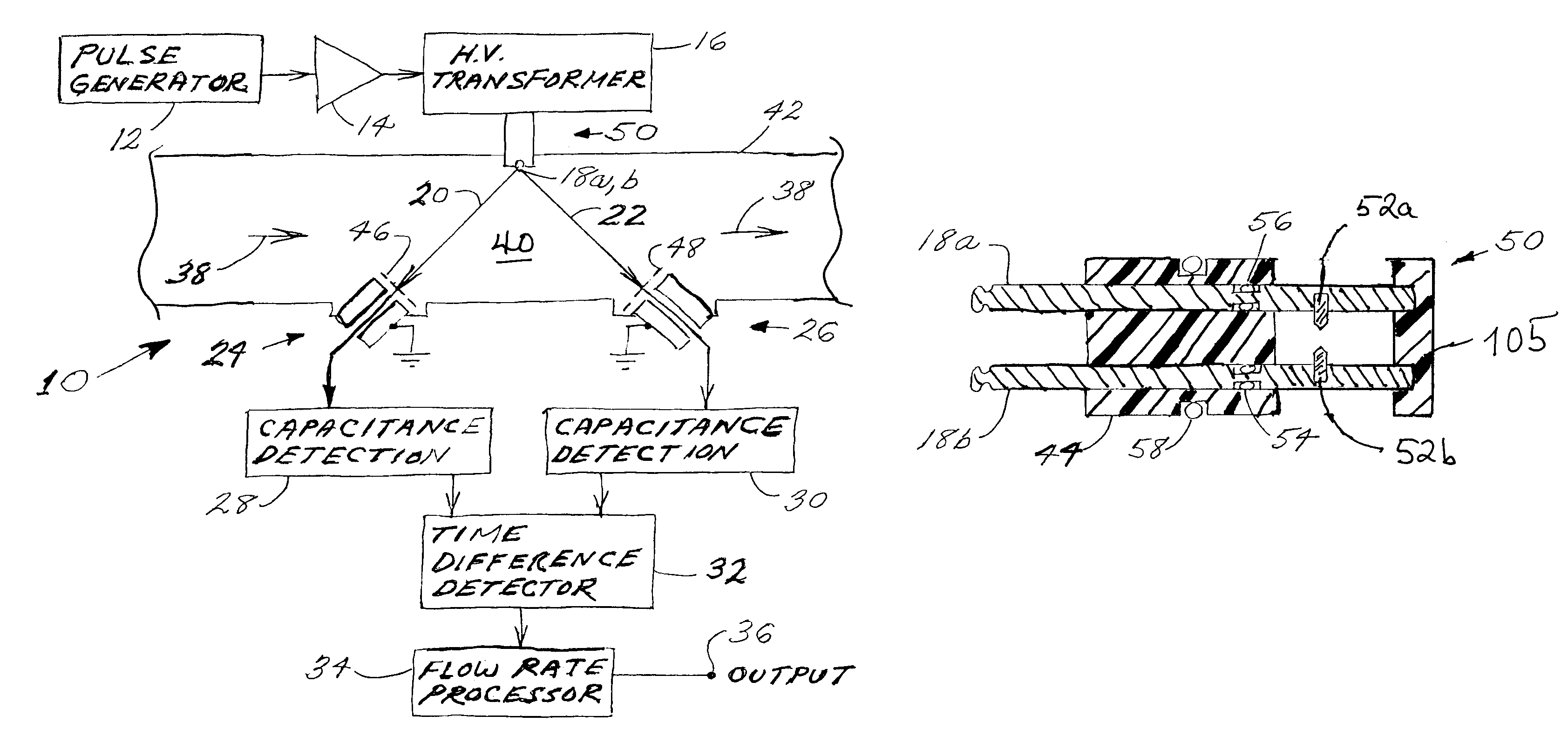
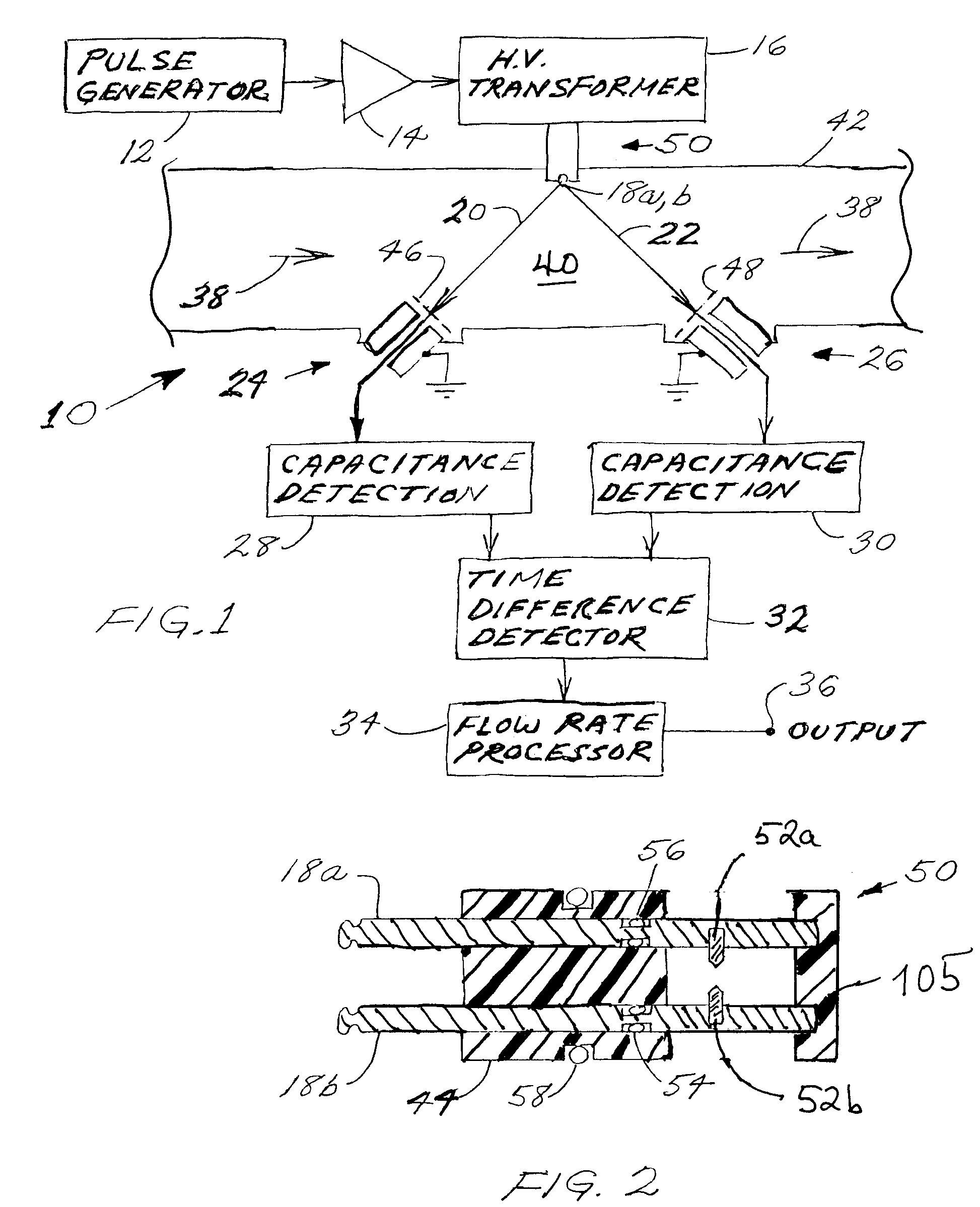
[0022]Turning now to FIG. 1, one finds a simplified block diagram of a preferred flow meter 10, of the present invention. A pulse generator 12 provides pulses to an amplifier 14 which is connected through a high voltage transformer 14 to a mutually insulated electrode pair 18a,b that comprise a portion of the acoustic source or transmitting transducer 50. If the fluid 40 is a gas, each pulse from the pulse generator 12 can produce an electrical discharge between the electrodes 18a,b. The resultant acoustic energy pulse is propagated through the fluid 40, as indicated by arrows 20, 22, to the flexible movable plate 46, 48 portions of the acoustic detectors or receiving transducers 24, 26. Each of the receiving transducers 24, 26 is connected to a respective capacitive detection circuit 28, 30. As is known in time-of-flight flow measurement, there is a difference in the upstream and downstream propagation times responsive to flow of fluid, indicated by the arrow 38, within a pipe or o...


PUM


Abstract

A time-of-flight flow meter that is particularly useful for measuring the flow of gases, such as steam, uses a spark gap periodically energized with an electrical pulse to generate an acoustic pulse. The pulse is detected by upstream and downstream acoustic detectors that may be capacitive transducers having flexible plates wetted on both sides by the fluid so that no external venting is required. The acoustic detectors may be electrically heated to avoid condensation effects. In some cases the interior of the pipe or other conduit is shaped near the source so as to define acoustic beams aimed at the detectors and so as to concentrate the received acoustic energy on the detectors.

Description

BACKGROUND OF THE INVENTION[0001]1. Field of the Invention[0002]The present invention relates to apparatus and methods of acoustic flow measurement using acoustic pulses to derive fluid flow rate.[0003]2. Background Information[0004]The prior art teaches ultrasonic time-of flight flow meters which rely on acoustic waves propagating in the flowing fluid. These devices usually use piezoelectric transducers to convert electrical drive signals to the propagated acoustic energy and to convert the received acoustic energy to electrical signals for processing to derive the fluid flow rate.[0005]Piezoelectric transducers are typically made of ceramic materials such as lead zirconate titanate which, while relatively economical and efficient, have mechanical properties that are significantly different from those of the flowing fluid with which they are interfacing. These differences result in poor acoustic coupling or impedance mismatching between the transducer and fluid, which in turn neces...

Claims


Application Information

Patent Timeline
Patent Type & Authority Patents(United States)
IPC IPC(8): G01F1/66
CPCG01F1/66
Inventor FELLER, MURRAY F
Owner ONICON INC
Why Eureka
Try Eureka