
System and method for moving material past an obstacle

a technology of material movement and obstacles, applied in the field of material movement systems and methods, can solve the problems of difficult to move large items throughout the building, difficult to the inability of carts to help users move objects around or past various obstacles, etc., to achieve the effect of reducing the area and space required to move objects and reducing the area needed to move objects

Active Publication Date: 2009-12-08
KOLESA TIMOTHY +1
View PDF7 Cites 14 Cited by
  • Summary
  • Abstract
  • Description
  • Claims
  • Application Information

AI Technical Summary

Benefits of technology

[0007]The present invention is directed to a system and method for moving material past an obstacle and / or for moving materials in areas of limited space. In one embodiment, the present invention provides a tilting bed cart / truck capable of carrying a load neither perpendicular nor parallel to the ground so that the area and space required to move an object is reduced. The tilting bed cart / truck may tilt the object loaded upon it so that the area needed to move an object is reduced. In one embodiment, the present invention enables objects to be moved in locations characterized by various physical restrictions such as limited height, width, and length dimensions that do not ordinarily allow for movement of larger sized objects. In another embodiment, the present invention may be configured so that as objects on the tilting bed cart / truck are tilted or moved in an upward and / or elevated direction, the load center of the object on the tilting bed cart / truck is maintained in order to provide stability to the object as the object is tilted and moved.
[0008]In one embodiment of the present invention, the tilting bed cart / truck may be configured so that it includes two base members, wheels, a lifting cylinder, a sliding member, and a holding framework. In such an embodiment, the wheels may be mounted to the two base members to allow the embodiment to be moved around. The sliding member may be configured so that it joins the two base members and allows the base members to move towards one another and allows the base members to move away from one another to ultimately change the length layout of the cart. The holding framework is configured to hold objects to be moved. Accordingly, the holding framework may take the form of any number of shapes or sizes to accommodate the moving of any number of objects, such as furniture, office cubicles, doors, refrigerators, sheet rock, plywood, paneling, and the like. The lifting cylinder may be configured so that it can be mounted to one base member and mounted to the holding framework so that it can move the holding framework in an upward and backward direction, such as tilting the object located on the holding framework in order to reduce the area needed to move an object and de-tilting the object or moving the object in a backward direction when the object has been moved around the obstacle.

Problems solved by technology

While hand carts, dollys, or trucks are often used to assist a mover in relocating objects, such carts are unable to help a user move objects around or past various obstacles.
For example, movement of objects around a jobsite, such as a construction worksite, may be very difficult due to various restrictions imposed by the jobsite, and ordinary hand trucks, dollys and carts provide no solution to the problem.
When a building is under construction, it is often difficult to move large items throughout the building, such as moving items from a first floor to an upper floor, due to physical restrictions of the building, such as wall heights, hall way dimensions, door openings, and the like.
When individuals attempt to use hand trucks, carts, and dollys to move large items through an area characterized by physical restrictions, such as a building under construction, the individual is presented with many roadblocks and restrictions.
However, the individual will often discover that the large item can not be transported in the limited space, such as the elevator designed for people.
Accordingly, the individual ultimately has to move the larger items, to the upper floors by physically carrying the item, without the assistance of a hand truck, dolly or cart, up the stairs, which is very labor intensive, time consuming and dangerous.

Method used


Image

  • System and method for moving material past an obstacle
  • System and method for moving material past an obstacle
  • System and method for moving material past an obstacle

Examples


Embodiment Construction

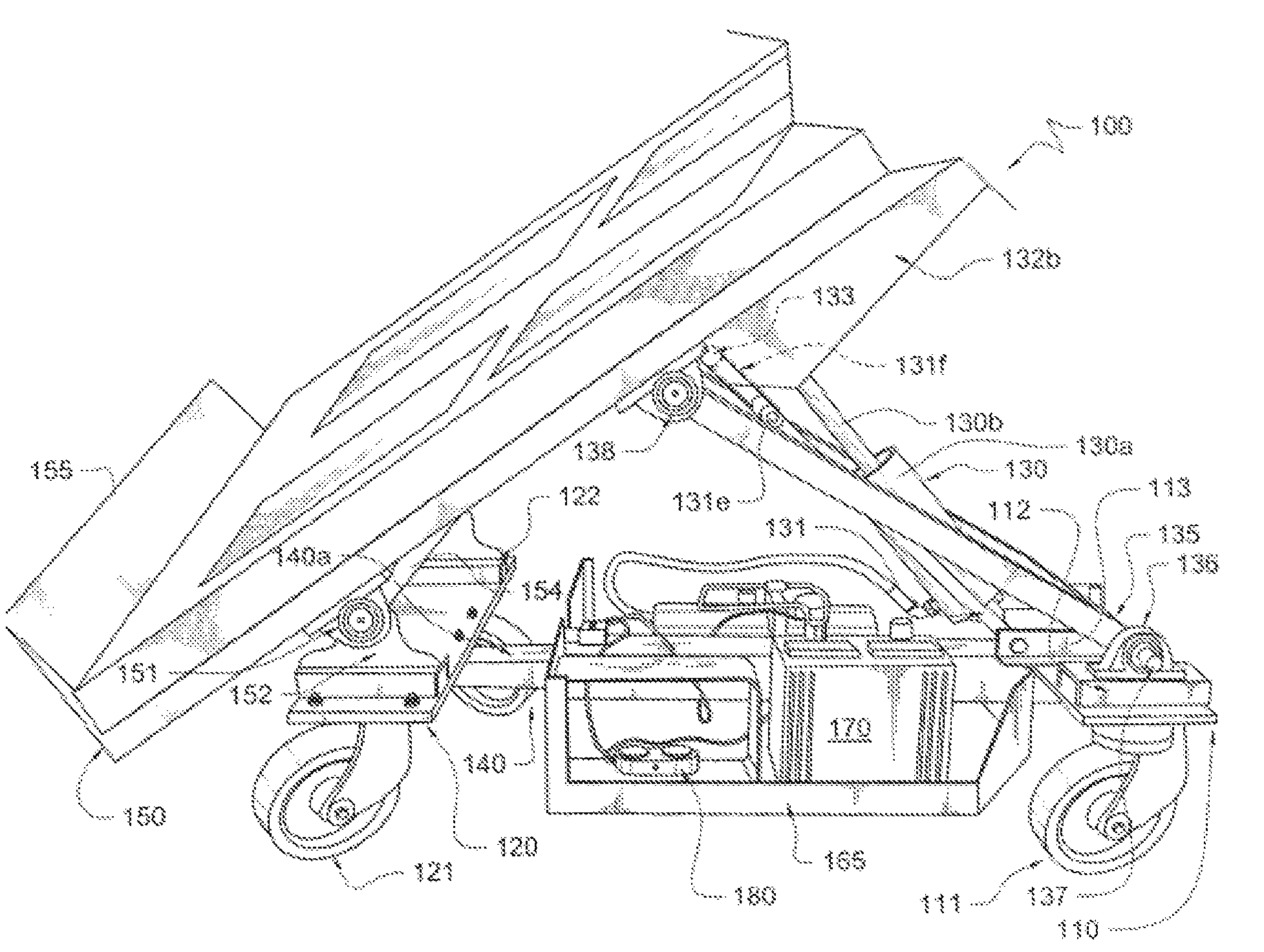
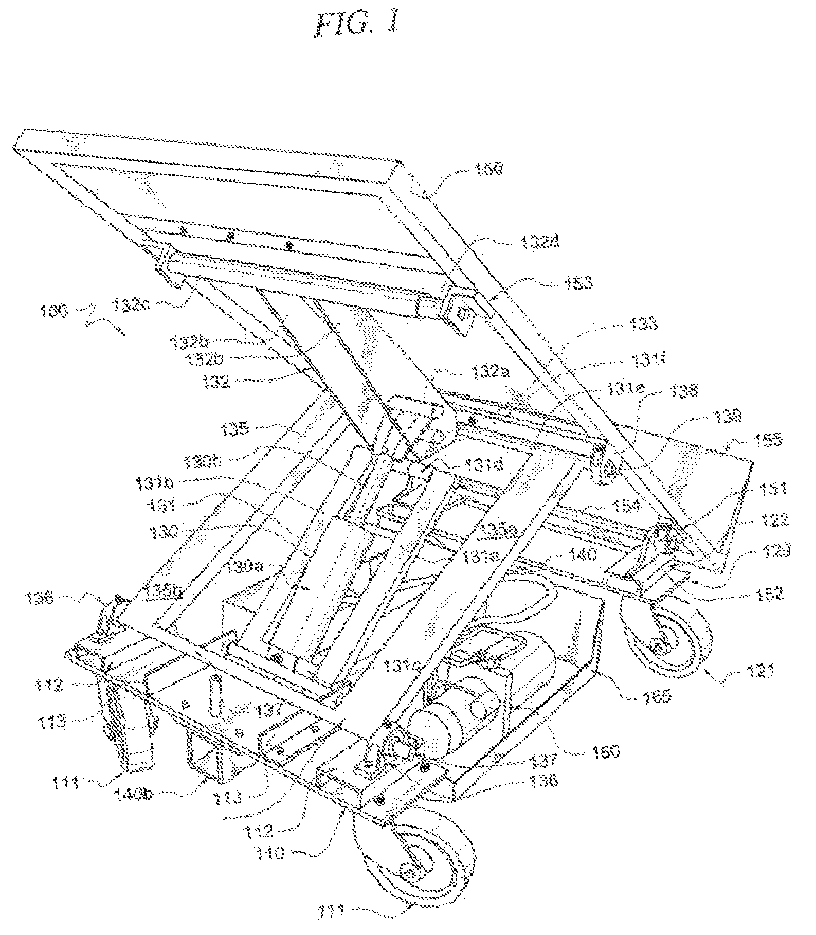
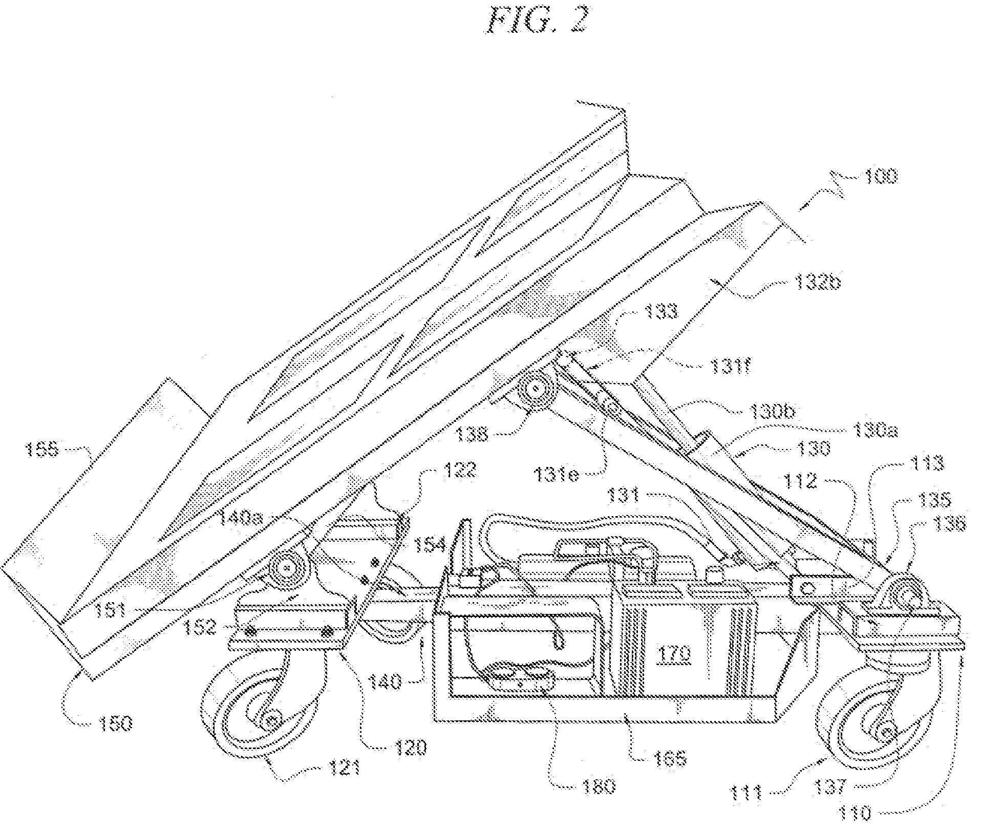
[0015]A preferred embodiment of a tilting bed-cart / truck adapted according to the present invention is shown generally as tilting bed-cart / truck 100 in FIGS. 1, 2 and 3. FIG. 1 illustrates a rear view of an embodiment of the present invention, FIG. 2 illustrates a side / frontal view of an embodiment of the present invention with a door located on the embodiment, and FIG. 3 illustrates a close up view of a portion of an embodiment of the present invention. Tilting bed-cart / truck 100 includes base member 110, wheels 111, base member 120, wheels 121, lift mechanism 130, framework support 135, mounts 136, mounts 138, sliding mechanism 140, framework 150, framework mount 151, mount member 152, lifting mechanism-framework mount 153, pump 160, power supply 170, and control station 180.

[0016]As illustrated in FIGS. 1 and 2, base members 110 and 120 are rectangular shaped. However, the present invention is not limited to this configuration as base members 110 and 120 may take the form of any ...


PUM


Abstract

A method and system are disclosed for moving material past an obstacle and / or for moving materials in areas of limited space. A user can move so that the area and space required to move an object is reduced. A user can utilize the system and method to load an object and then tilt the object to be moved so that the area needed to move an object is reduced. After the object has been tilted, a user can move the object in locations characterized by various physical restrictions such as limited height, width, and length dimensions that do not ordinarily allow for movement of larger sized objects.

Description

TECHNICAL FIELD[0001]The present invention relates, in general to material movement systems and methods, and more specifically to a system and method for moving material past an obstacle and / or for moving materials in areas of limited space.BACKGROUND OF INVENTION[0002]Moving objects from one location to another location can be simplified with the use of some type of device, such as a hand cart, a hand truck, a dolly and the like. Such devices are often used everyday in a variety of locations for a variety of purposes, such as in factories, warehouses, offices, outdoors, homes and the like. These hand trucks and carts come in different sizes and shapes, depending on the nature of the object to be moved. For example, when large objects are moved, such as refrigerators, stoves, large boxes and the like, a mover may move the large object and position the large object on the dolly or cart so that the mover can move the large object to the desired destination with the use of the dolly or...

Claims


Application Information

Patent Timeline
Patent Type & Authority Patents(United States)
IPC IPC(8): B62B1/04
CPCB62B3/08B62B3/108B62B3/10B62B2203/07
Inventor KOLESA, TIMOTHYPICK, RANDAL
Owner KOLESA TIMOTHY
Learn More