Connector having floating structure

a technology of connecting structure and floating structure, which is applied in the direction of incorrect coupling prevention, coupling device connection, electrical apparatus, etc., can solve the problems of miniaturization, assembly and miniaturization problems, and damage to the connecting structure, and achieves low part count, simple structure, and easy assembly

Inactive Publication Date: 2009-12-08
SMK CORP
View PDF10 Cites 45 Cited by
  • Summary
  • Abstract
  • Description
  • Claims
  • Application Information

AI Technical Summary

Benefits of technology

[0017]a connector moveably mounted in a cradle housing, a part of this connector that connects to and detaches from another connector facing, through a spacing, a connector-mounting window of the cradle housing, and the connector on the moveable side being moveable freely within the range of the spacing; wherein an elastic member of flexible material is provided on the exterior of the moveable-side connector, the connector provided with this elastic member closely contacts and is housed in a housing part formed in the cradle housing, and an elastic member restoring force, acting when coupling between the moveable-side connector and another connector is released, causes the moveable-side connector to return to the original position of the connector.
[0022]The elastic member of flexible material may be provided on the exterior of the moveable-side connector, the connector provided with this elastic member closely contacts and is housed in a housing part formed in the cradle housing, and an elastic member restoring force, acting when coupling between the moveable-side connector and another connector is released, causes the moveable-side connector to return to the original position of the connector, enables the provision of a connector having a floating structure and also having a simple structure, a low part count, being easy to assemble and capable of being miniaturized.
[0023]On the exterior of the connector housing comprising the moveable-side connector, the elastic member may be formed by the secondary molding using flexible material that has elasticity, thereby enabling the elastic member to be configured easily with secondary molding using flexible material having elasticity on the connector housing of the primary molding.
[0024]On the exterior of the connector housing comprising the moveable-side connector, the elastic member may be formed by secondary molding using flexible material that has elasticity such that the exterior surface has a plurality of protrusions, and the moveable-side connector is housed such that the protrusions are in close contact with the interior of the housing part, enables the amount of movement to be adjusted easily according to the size of the protrusions.
[0026]In the connector having a floating structure with two connectors separated by a certain distance, the two connectors may be moveably mounted in a cradle housing, parts of the moveably mounted connectors that connect to and detach from another connector face, through a spacing, a respective connector-mounting window of the cradle housing, and the two moveably mounted connectors may move freely within the range of the spacing. An elastic member of flexible material is provided on the exterior of each moveably mounted connector. Each connector provided with this elastic member closely contacts and is housed in a respective housing part formed on the cradle housing, and an elastic member restoring force, acting when coupling between the moveably mounted connectors and other connectors is released, causes the two moveably mounted connectors to return to the original position of the connectors, thereby enabling reliable mating and connecting even in the case where there are two connectors separated by a certain distance on both the electronic device-side and the cradle-side and both of the connectors move.
[0027]In the connector having a floating structure with two movably mounted connectors, the moving distances according to the elastic members in the two moveably mounted connectors may be set to a smaller value for the side that first touches another connector and to a larger value for the side that subsequently touches the other connector, thereby enabling reliable mating and connecting even in the case where the two connectors have different contact heights.

Problems solved by technology

In the case where digital cameras, cell phones, digital video cameras and other electronic devices transmit and receive information or recharge while in an interconnected state with plugs or multi-pin connectors, if the plug or multi-pin connectors are rigidly attached to the device there is a risk that the connectors may become damaged due to twisting when mated together.
The following types of problems existed in connectors having a conventional floating structure.
However, the rather complex structures of the four S-shaped elastic members 19, the downward-facing boss 23, and the cylindrical part 21 of the connector housing 14 and so on present some problems for miniaturization.
However, the rather complex structure and large number of component parts and present some problems for assembly and miniaturization.
(3) The structure shown in FIG. 5 is simple and can be miniaturized, but has the problems of only being capable of handling displacement over the range of the tapered faces and of being unable to return to the original position when the connectors are unplugged.

Method used


Image

  • Connector having floating structure
  • Connector having floating structure
  • Connector having floating structure

Examples


embodiment 1

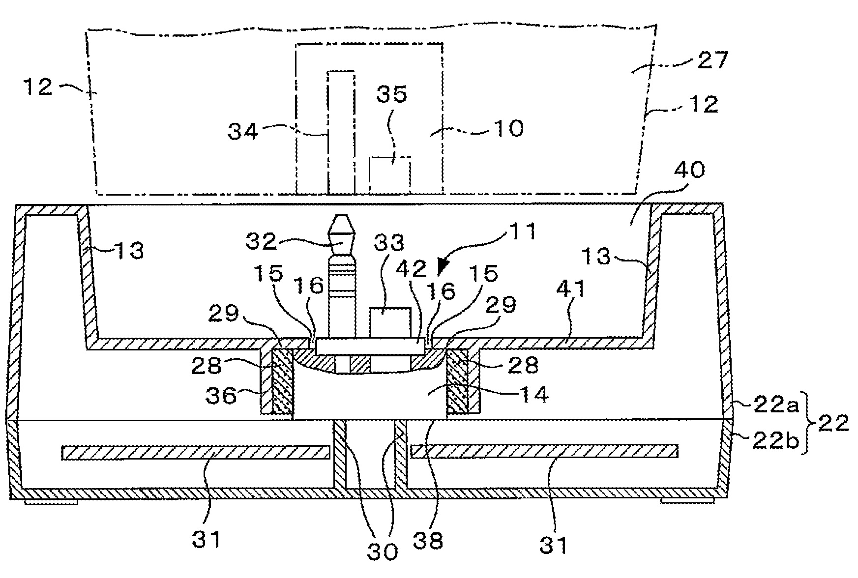
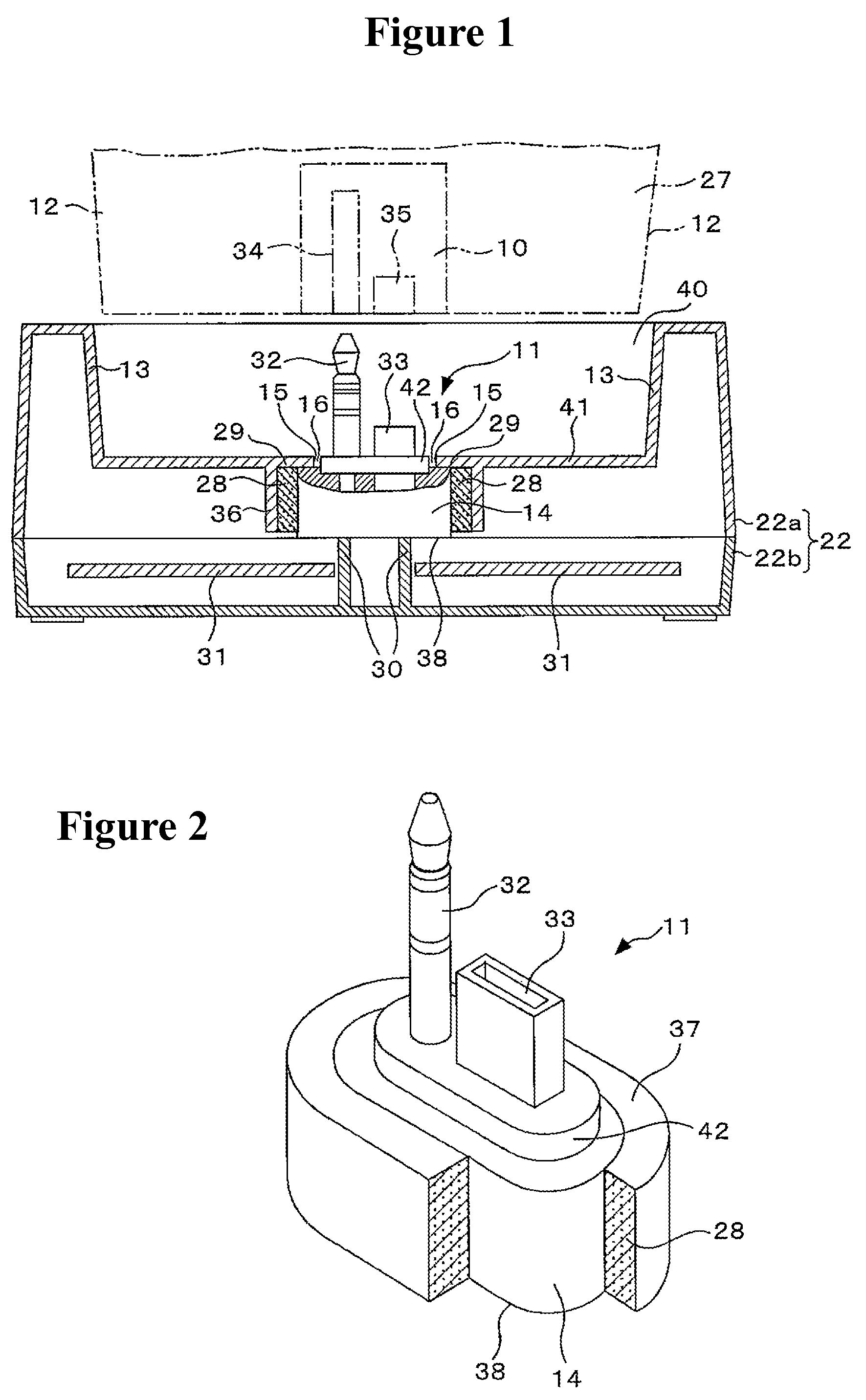
[0050]In FIG. 2, reference numeral 11 denotes a cradle-side connector of the present invention, and this cradle-side connector 11 includes an attachment base 42 integrally formed with a pin plug 32 and a multipole socket 33. The cradle-side connector also includes structure comprising a lead wire (not shown) that preferably is integrally formed by primary molding of a connector housing 14, and the outer periphery of the connector housing 14 is covered by an elastic material 28 of rubber or the like that is flexible and elastic, and which is preferably formed by secondary molding.

[0051]More specifically, the structure including of the pin plug 32, the multipole socket 33, the lead wire and so on integrally formed with the attachment base 42 is covered by a primary molding of the connector housing 14 that is preferably made of hard plastic or the like so that a stepped part of the top face of the attachment base 42 protrudes slightly therethrough. Excluding a top face part 37 and a bo...

embodiment 2

[0061]A second embodiment of the present invention is described below with reference to FIGS. 2 to 4.

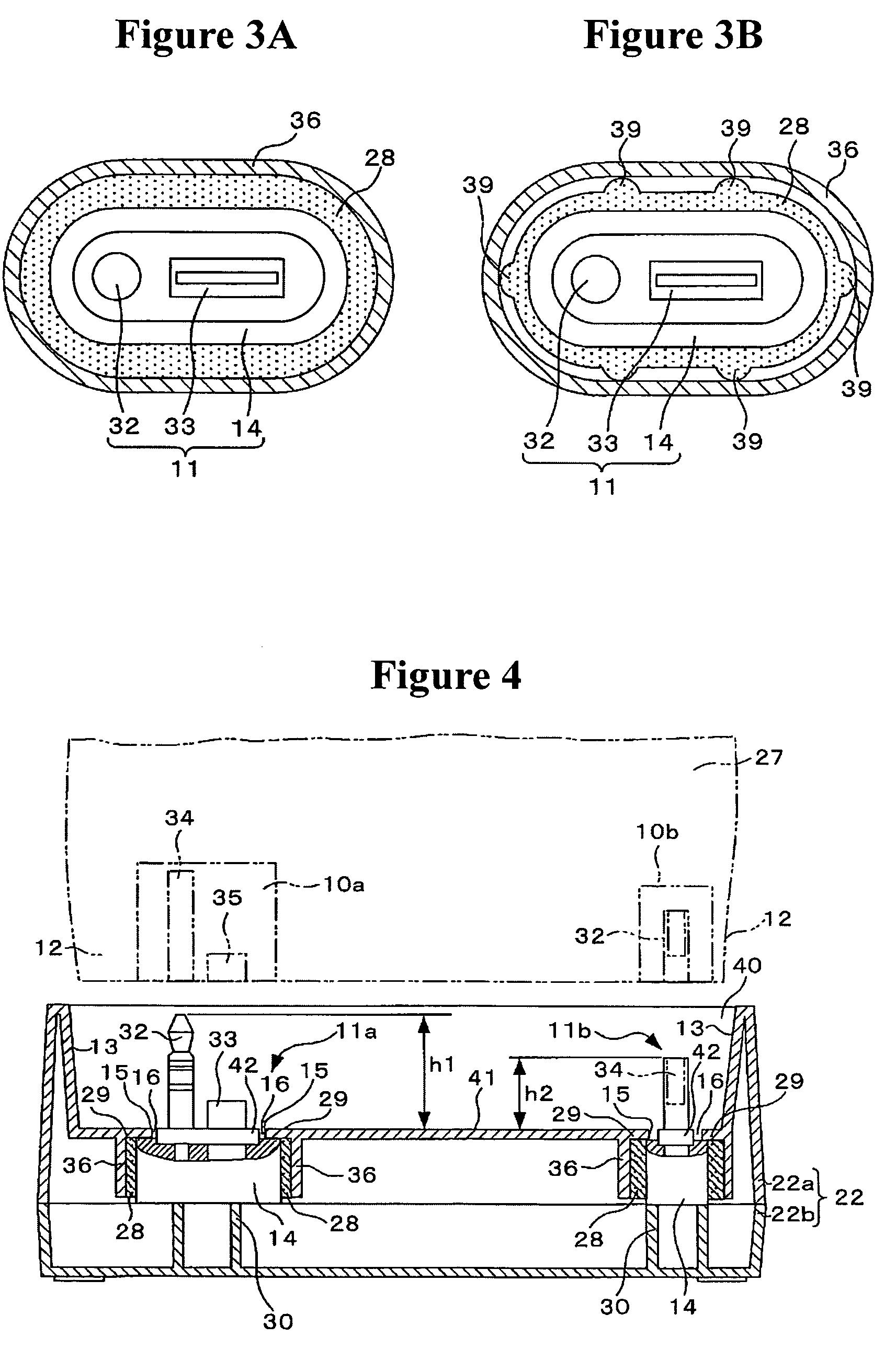
[0062]In this example, for example, an electronic device-side first connector 10a having a pin socket 34 for audio transmission-use and a multipole plug 35 for data transmission-use and an electronic device-side second connector 10b having a pin plug 32 for power supply-use are disposed a distance apart on the electronic device 27, and also a cradle housing 22 that mates and connects to the electronic device 27 is provided with a cradle-side first connector 11a and a cradle-side second connector 11b.

[0063]In such an example, if the height h1 of the pin plug 32 of the cradle-side first connector 11a is greater than the height h2 of the pin socket 34 of the cradle-side second connector 11b, since mating of the pin plug 32 of the cradle-side first connector 11a with the pin socket 34 of the electronic device-side first connector 10a occurs earlier than mating of the pin socket 34 of th...


PUM


Abstract

A connector assembly having a floating structure includes a connector moveably mounted in a cradle housing. A part of this connector connects to and detaches from another connector facing, through a spacing, a connector-mounting window of the cradle housing. The connector on the moveable side is moveable freely within the range of the spacing. An elastic member of flexible material is provided on the exterior of the moveable-side connector and closely contacts and is housed in a housing part formed in the cradle housing. An elastic member restoring force, acting when coupling between the moveable-side connector and the other connector is released, causes the moveable-side connector to return its original position in the cradle housing.

Description

CROSS-REFERENCE TO RELATED APPLICATION[0001]This application claims the benefit under 35 U.S.C. § 119 of Japanese Patent Application No. 2008-108874, filed on Apr. 18, 2008, which is hereby incorporated by reference herein in its entirety.FIELD OF THE INVENTION[0002]The present invention relates to a connector having a floating structure such that when a connector provided on a digital camera, cell phone, digital video camera or other electronic device is coupled to a connector provided on the cradle of a charging device or the like, one connector is provided with freedom to move forwards, backwards, left and right, and positional displacement of the coupling between connectors is absorbed.BACKGROUND OF THE INVENTION[0003]In the case where digital cameras, cell phones, digital video cameras and other electronic devices transmit and receive information or recharge while in an interconnected state with plugs or multi-pin connectors, if the plug or multi-pin connectors are rigidly atta...

Claims


Application Information

Patent Timeline
Patent Type & Authority Patents(United States)
IPC IPC(8): H01R13/64
CPCH01R13/6315
Inventor MATSUDA, TAKESHIKOMURO, MASAJI
Owner SMK CORP
Why Eureka
Try Eureka