Electric submarine power cable and system for direct electric heating

a technology of power cable and system, applied in the direction of power cables, cables, insulated conductors, etc., can solve the problems of affecting the effectiveness of the system, unable to mount simultaneous current supply cables, and inability to provide insulation layers on high-voltage transmission lines

Active Publication Date: 2009-12-08
NEXANS
View PDF13 Cites 11 Cited by
  • Summary
  • Abstract
  • Description
  • Claims
  • Application Information

AI Technical Summary

Benefits of technology

[0013]In the new design as proposed above, with metal wires as a core strength member inside the conductor elements, substantial advantages are obtained. One advantage consists therein that the strength member is protected against any damage, but perhaps more important,

Problems solved by technology

Moreover, these high voltage transmission lines are not provided with any insulation layers along their length.
For a retrofit installation of a direct electric heating system, however, such simultaneous mounting of the current supply cable is not feasible.
In the case of

Method used


Image

  • Electric submarine power cable and system for direct electric heating
  • Electric submarine power cable and system for direct electric heating

Examples


Embodiment Construction

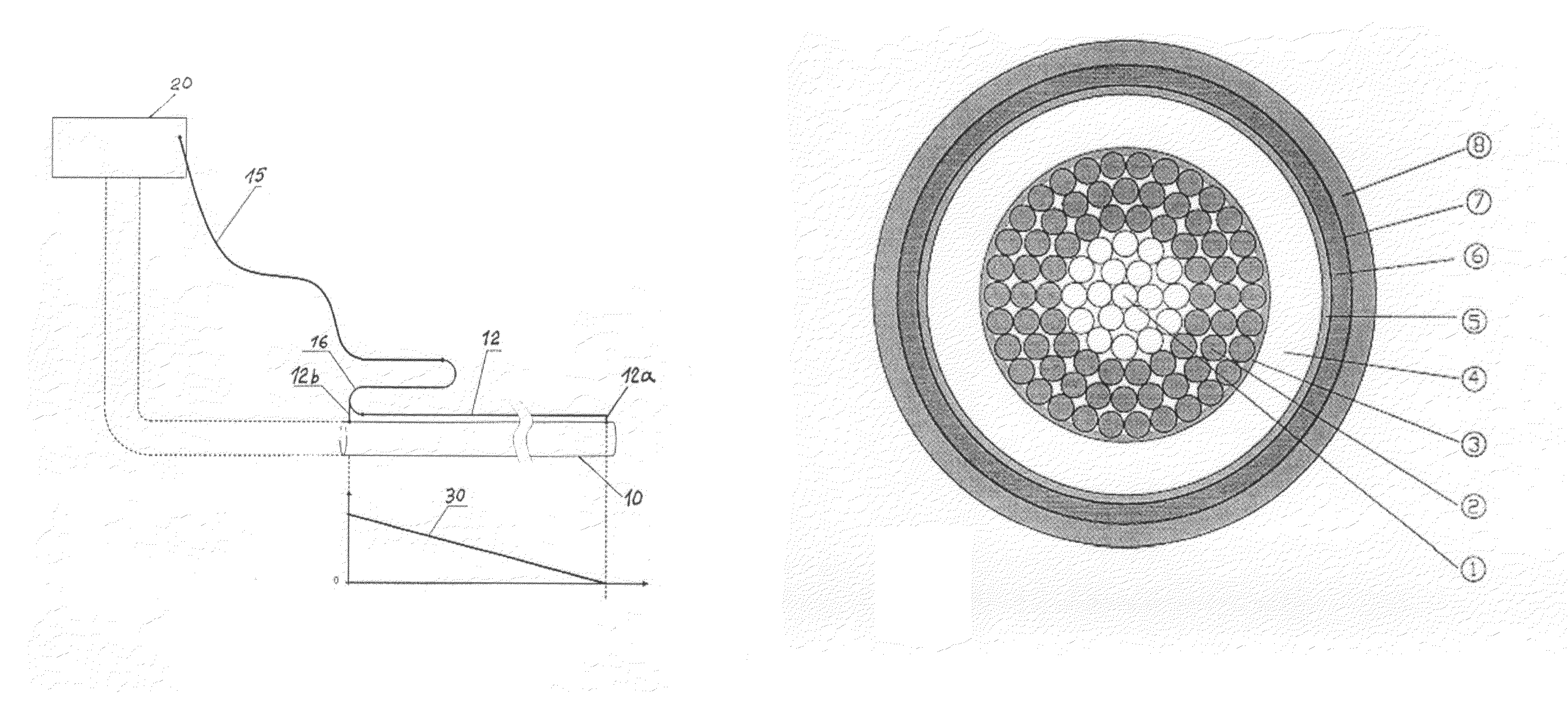
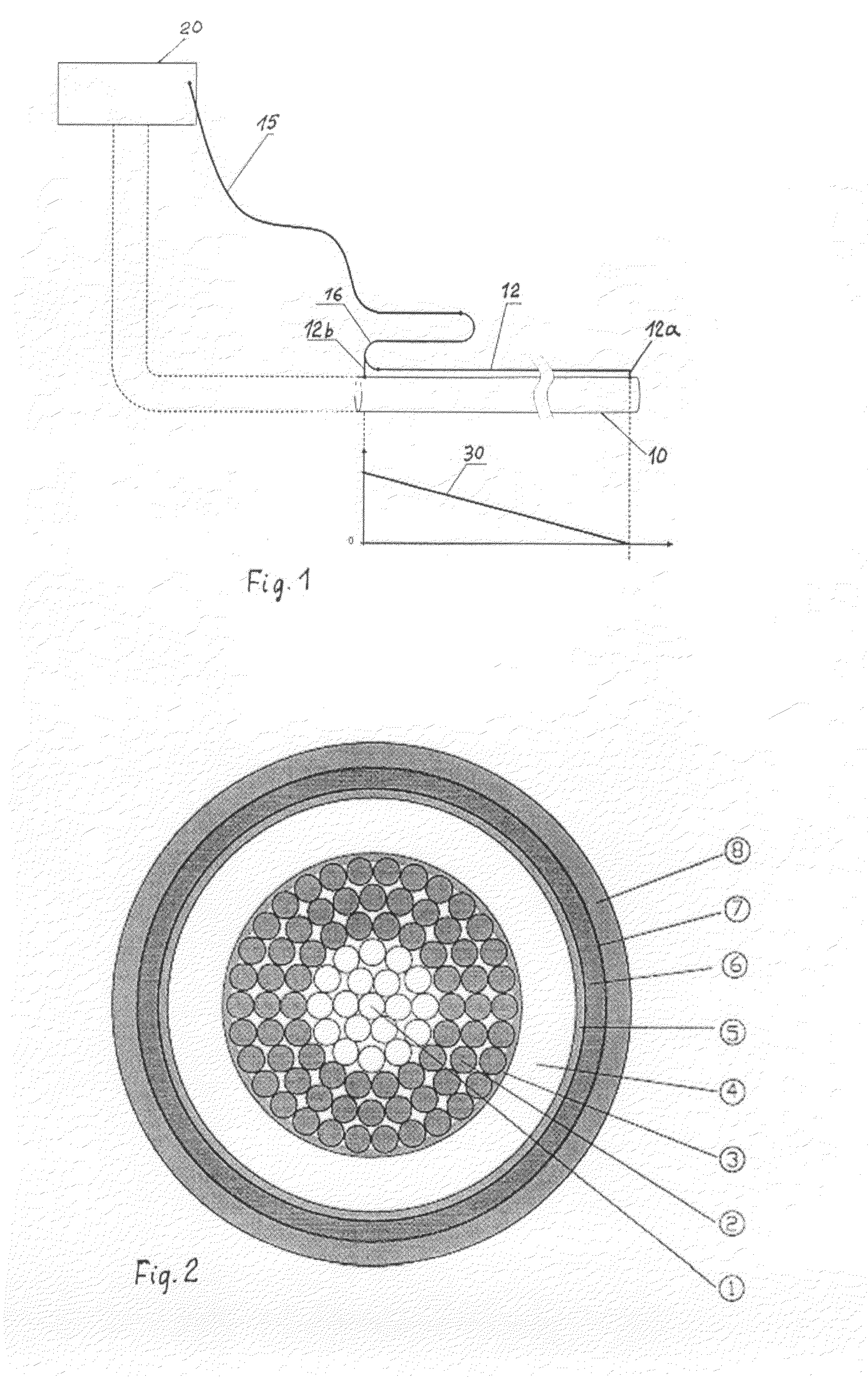
[0024]In the arrangement illustrated in FIG. 1 there is a subsea pipeline 10, which may be of considerable length. A piggyback cable 12 is installed along the pipeline 10 or possibly a section thereof. The cable 12 may be of a design as explained below with reference to FIG. 2 of the drawings. At 12a there is shown an

[0025]electrical connection point between the piggyback cable and the pipeline, for current supply to the latter at this remote end.

[0026]An electric power supply unit 20 arranged on a topside structure comprised by the total plant or platform concerned. From unit 20 there is a two-conductor supply cable or riser cable 15 extended down to the subsea installation concerned, where there is provided an armoured feeder cable 16, also being a two-conductor cable or possibly two single-core cables.

[0027]One of the feeder cable conductors is connected to the pipeline surface at 12b whereas the other feeder conductor is connected to the first end of the piggyback cable 12—in th...


PUM


Abstract

An electric submarine power cable, in particular for use in hydrocarbon pipeline heating systems and adapted to be installed as a piggyback cable on the pipelines, having a multi-wire stranded conductive core with an outer insulation and at least one outer protective sheath as well as armoring means. The armoring means are incorporated in the conductive core as integral tensile strength wire elements. Moreover, a hydrocarbon pipeline heating system as such, having this submarine power cable.

Description

RELATED APPLICATION[0001]This application is related to and claims the benefit of priority from Norwegian Patent Application No. 2006 0760, filed on Feb. 17, 2006, the entirety of which is incorporated herein by reference.FIELD OF THE INVENTION[0002]The present invention in one aspect relates to an electric power cable of a new design, in particular for submarine use in hydrocarbon pipeline heating systems.BACKGROUND OF THE INVENTION[0003]Electric power cables of various designs for a number of different purposes and applications have been known for a long time. In particular, such cables usually comprise an armouring of a strong material that will contribute substantially to the mechanical strength and protection of the cable. Tensile strength is often essential in this connection, and steel of selected qualities is well known as an armouring material. Such armouring of known cable designs is wound as one or more outer layers in order to protect inner insulation layers and current ...

Claims


Application Information

Patent Timeline
IPC IPC(8): H01B7/18F16L53/37
CPCF16L53/007H01B7/14H01B7/223H05B3/56H05B2214/03F16L53/37
Inventor ESPEN, OLSEN
Owner NEXANS
Why Eureka
Try Eureka