Multi-homing using controlled route leakage at a backup service provider

a backup service provider and multi-homing technology, applied in the field of computer networks, can solve the problems of unfavorable large-scale configuration over the internet, undesired asymmetric network traffic pattern, and often arise in the conventional multi-homed topology, and achieve the effect of improving bandwidth utilization and fast network convergen

Active Publication Date: 2009-12-08
CISCO TECH INC
View PDF28 Cites 25 Cited by
  • Summary
  • Abstract
  • Description
  • Claims
  • Application Information

AI Technical Summary

Benefits of technology

[0026]Advantageously, the present invention enables a customer site to be multi-homed to primary and secondary networks without resulting in asymmetric traffic patterns. More specifically, while the customer site's route is suppressed by the secondary network, inbound network traffic addressed to the customer site is initially directed through the primary network. However, once the secondary network unsuppresses the customer site's route, and therefore advertises the customer site's route as being reachable through the secondary network, inbound traffic to the customer site can be redirected to the secondary network due to conventional longest prefix matching algorithms employed in the computer network, i.e., the secondary network's “more specific” customer-site route becomes a preferred route over the primary network's aggregated (“less specific”) route.
[0027]Further, the inventive technique permits return-path load balancing so network nodes in the secondary network can forward data directly to the customer site without first having to route the data to the primary network. The inventive technique also does not require any special customer-site configuration. Additionally, faster network convergence and better bandwidth utilization can be realized in the secondary network in response to the primary network losing connectivity with the customer site and / or the backbone network. That is, border routers in the secondary network can quickly unsuppress the customer site's route simply by removing the route's associated no-export attribute rather than having to propagate the customer-site route throughout the secondary network, e.g., using conventional iBGP update messages.

Problems solved by technology

Problems often arise in this conventional multi-homed topology.
This results in an undesired asymmetric network traffic pattern at the customer site 140.
Such large-scale configuration is impractical over the Internet, which consists of a large number of independently managed networks and subnetworks.
Further, the solution is limited to “square” topologies as described in RFC 1998.
Accordingly, the local-preference solution has limited use.

Method used


Image

  • Multi-homing using controlled route leakage at a backup service provider
  • Multi-homing using controlled route leakage at a backup service provider
  • Multi-homing using controlled route leakage at a backup service provider

Examples


Embodiment Construction

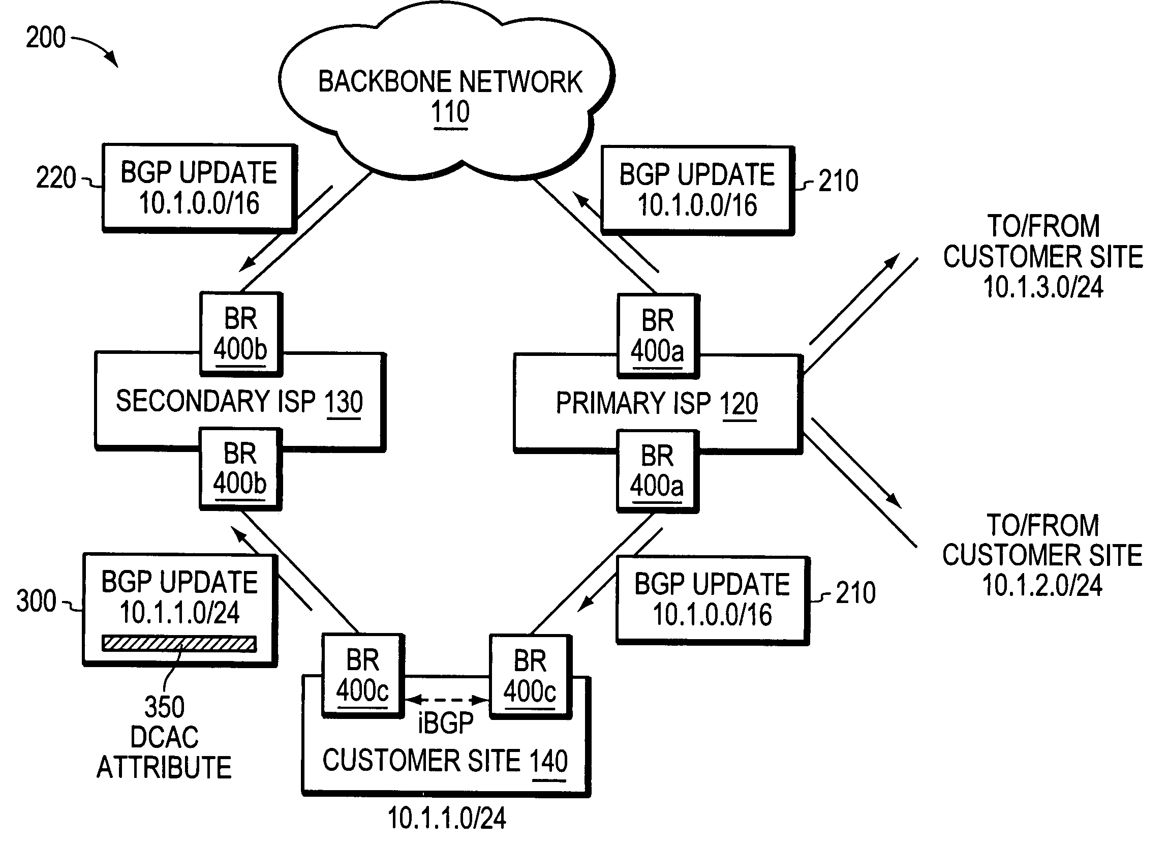
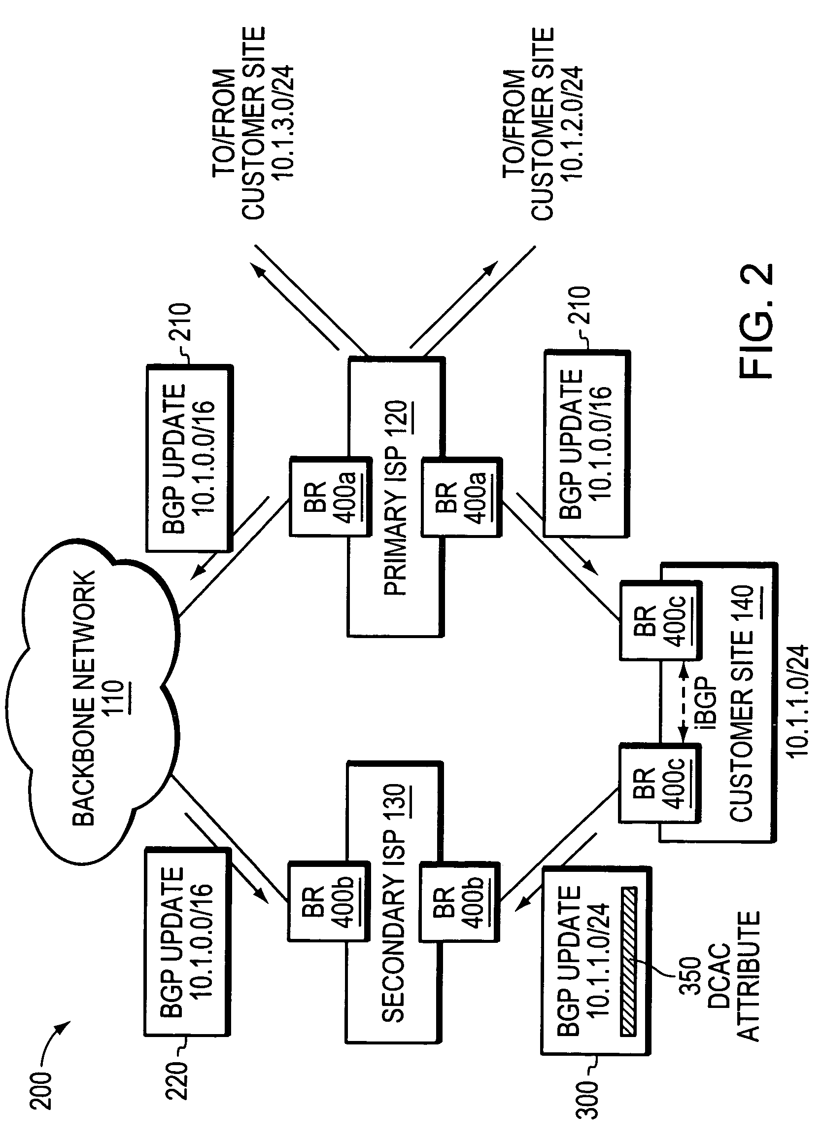
[0039]FIG. 2 illustrates an exemplary multi-homed computer network 200 in which route aggregation may be employed in accordance with the illustrative embodiments of the invention. For ease of illustration and description, it is assumed that FIG. 2 illustrates the network after the primary ISP 120 has allocated blocks of IP addresses to its neighboring customer sites. For example, as shown, the primary ISP allocated the block of IP addresses 10.1.1.0 / 24 to the multi-homed customer site 140, and allocated the blocks of IP addresses corresponding to 10.1.2.0 / 24 and 10.1.3.0 / 24 to its other neighboring customer sites (not shown). Although this illustrative embodiment assumes that each customer site has been allocated a single range of IP addresses (i.e., a single address prefix), those skilled in the art will appreciate that each customer site may be allocated one or more different blocks of IP addresses (i.e., one or more address prefixes).

[0040]The primary ISP 120 may aggregate at ...


PUM


Abstract

A technique for implementing route aggregation in a computer network containing a multi-homed customer site connected to primary and second networks, which in turn are both connected to a common “backbone” network. According to the technique, the primary network allocates a block of network addresses for the customer site, and the customer site notifies the secondary network of its allocated addresses. The secondary network first determines whether the primary network has already advertised an aggregated route which incorporates the customer site's route. If so, the secondary network “suppresses” (i.e., does not advertise) the customer site's route. The secondary network only “unsuppresses” the customer site's route if it detects that the primary network has lost connectivity to the customer site and / or the backbone network.

Description

FIELD OF THE INVENTION[0001]This invention relates generally to computer networks, and, more specifically, to a technique for implementing route aggregation in a multi-homed computer network.BACKGROUND OF THE INVENTION[0002]Networks and Subnetworks[0003]A computer network is a geographically distributed collection of interconnected subnetworks, such as local area networks (LAN), that transport data between network nodes. As used herein, a network node is any device adapted to send and / or receive data in the computer network. The network topology is defined by an arrangement of network nodes that communicate with one another, typically through one or more intermediate network nodes, such as routers and switches. In addition to intra-network communications between nodes located in the same network, data also may be exchanged between nodes located in different networks. To that end, a “border router” located at the logical outer-bound (or “edge”) of a first computer network may be adap...

Claims


Application Information

Patent Timeline
Patent Type & Authority Patents(United States)
IPC IPC(8): H04J3/26H04H20/71
CPCH04L45/02H04L45/033
Inventor RAZA, SYED KHALID
Owner CISCO TECH INC
Why Eureka
Try Eureka