

Turbine heat shield with ribs
a technology of heat shield and turbine, which is applied in the direction of positive displacement liquid engines, machines/engines, pumping machines, etc., can solve the problems of oil bypass, particularly into the turbine housing, and the high temperature of the turbine to not be allowed to adversely affect the lubricating oil in the bearing housing, so as to prevent the leakage of lubrican
- Summary
- Abstract
- Description
- Claims
- Application Information
AI Technical Summary
Benefits of technology
Problems solved by technology
Method used
Image

Examples
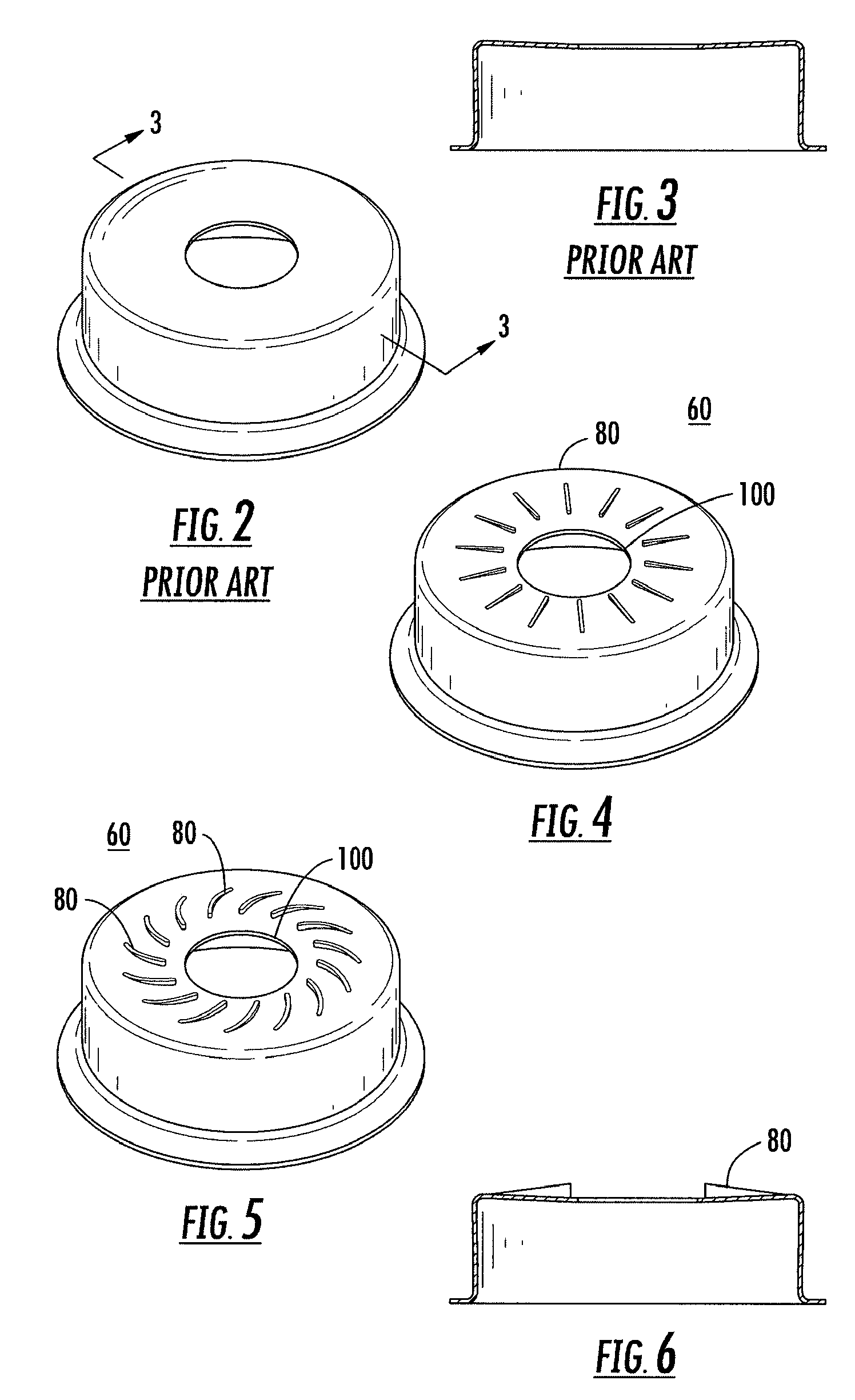
first embodiment
[0053]In the invention, the ribs have a straight shape radiating out from the center of the heat shield.
second embodiment
[0054]In the present invention, the ribs have a curved shape.
[0055]In a less preferred embodiment of the invention, the ribs have a circular shape concentric with the center of the heat shield, as is shown in FIG. 7.
[0056]In another less preferred embodiment of the present invention, the ribs may have a triangular (see FIG. 8) or rectangular (see FIG. 9) or square (see FIG. 10) shape centered about the center of the heat shield.
[0057]The heat shield, according to the present invention, may be a machined shield or a stamped shield.
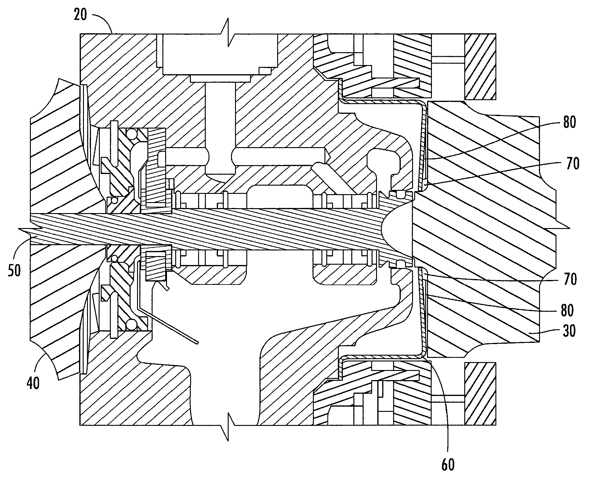
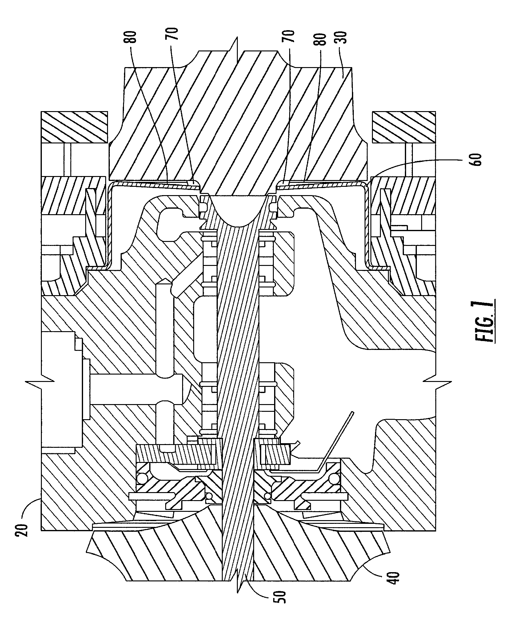
[0058]Furthermore, the present invention contemplates a method of preventing a lubricant leak in a turbocharger comprising the steps of:[0059]a) providing a turbocharger comprising:
[0060]a turbocharger housing including a compressor housing, a bearing housing and a turbine housing;
[0061]a turbine wheel located in said turbine housing;
[0062]a compressor wheel located in said compressor housing;
[0063]a shaft extending through the bearing housing and connectin...
PUM
 Abstract
Description
Claims
Application Information