Micro-manipulator

a micro-manipulator and hand-held technology, applied in the field of micro-manipulators, can solve the problems of inability of end-effecters to properly grip the material, incorrect gripping position of the micro-material, and add to the difficulty of operation, so as to secure and more quickly grip the micro-material, secure and quick grip

Inactive Publication Date: 2009-12-15
NISCA KK
View PDF16 Cites 2 Cited by
  • Summary
  • Abstract
  • Description
  • Claims
  • Application Information

AI Technical Summary

Benefits of technology

[0012]In the first aspect, after the fixed end effecter is contacted with the micro-material, the actuator is driven, causing the leading end of the movable end effecter to come into contact with the leading end of the other, fixed end effecter, thereby gripping the micro-material between the end effecters. Therefore, the micro-manipulator of the present invention does not require an additional actuator or a clutching mechanism. The positions of the end effecters with regard to the micro-material being gripped do not need to be readjusted, and it is possible to securely and rapidly grip the micro-material within the visual field of a microscope.
[0015]In doing so, the rigidity of the end effecters also decreases. For example, if it is necessary to work with a micro-material such as a cell in a liquid, a problem may arise that the end effecters bend under the viscous resistance of the liquid. Thus, by forming the areas between the fastening locations and the leading ends of the end effecters of the fixed and movable fingers to have reduced diameters, it is possible to create leading ends having the same dimensions as the micro-material while maintaining a rigid structure.
[0018]Furthermore, the handling mechanism has an adjusting mechanism for adjusting so that the sectioned surfaces of the leading ends of the end effecters of the fixed and movable fingers can touch each other. This makes it possible to align the positions of the sectioned surfaces of the leading ends of the end effecters without the limitations in material as in the conventional technology, or, without having to employ high precision forming techniques.
[0020]By providing a posture changing mechanism for changing the posture of the end effecters of the fixed and movable fingers with regard to the micro-material by rotating the handling mechanism around the center of the leading ends of the end effecters of the fixed and movable fingers, it is possible to change the posture of the end effecters of the fixed and movable fingers with regard to the micro-material and thus more securely and more quickly grip the micro-material.
[0021]According to the invention, after the fixed end effecter is contacted with the micro-material, the actuator is driven, causing the leading end of the movable end effecter to come into contact with the leading end of the end effecter of the fixed finger, thereby gripping the micro-material between the end effecters of the fixed and movable fingers. Therefore, no additional mechanisms, such as an actuator or clutching mechanism, are required. It is therefore possible to securely and quickly grip a micro-material within the visual field of a microscope without having to readjust the end effecter positions with regard to the micro-material undergoing the gripping operation.

Problems solved by technology

If the action for gripping of the end effecters follows a circular locus, the gripping position will be incorrect with regard to the micro-material.
Thus, it will be impossible for the end effecters to properly grip the material.
This requires the addition of an actuator or clutching mechanism, or other additional mechanisms, which also adds to the difficulty of operation.
Furthermore, there is a limit to the materials that can be used to configure two gripping fingers using one elastic member, and high forming precision has been required.

Method used


Image

  • Micro-manipulator
  • Micro-manipulator
  • Micro-manipulator

Examples


Embodiment Construction

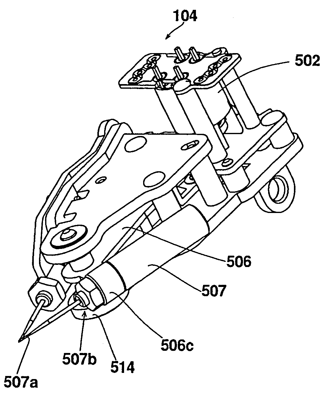
[0032]Hereunder, a micro-manipulator according to the present invention applied to a micro-material handling system for handling a micro-material, such as a cell or a micro-component, will be explained with reference to the accompanying drawings.

System Configuration

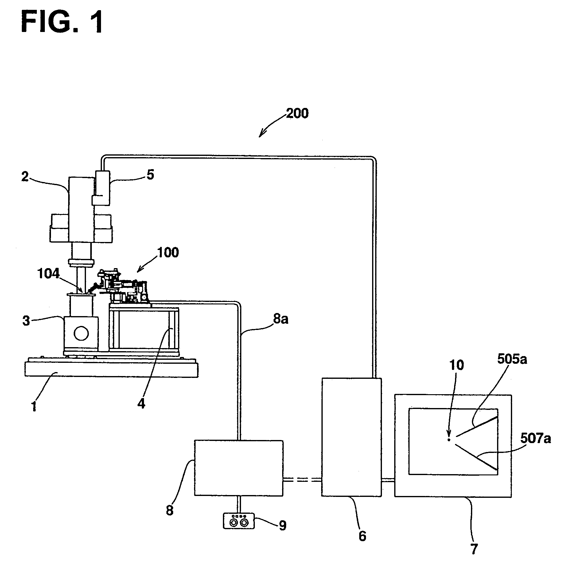
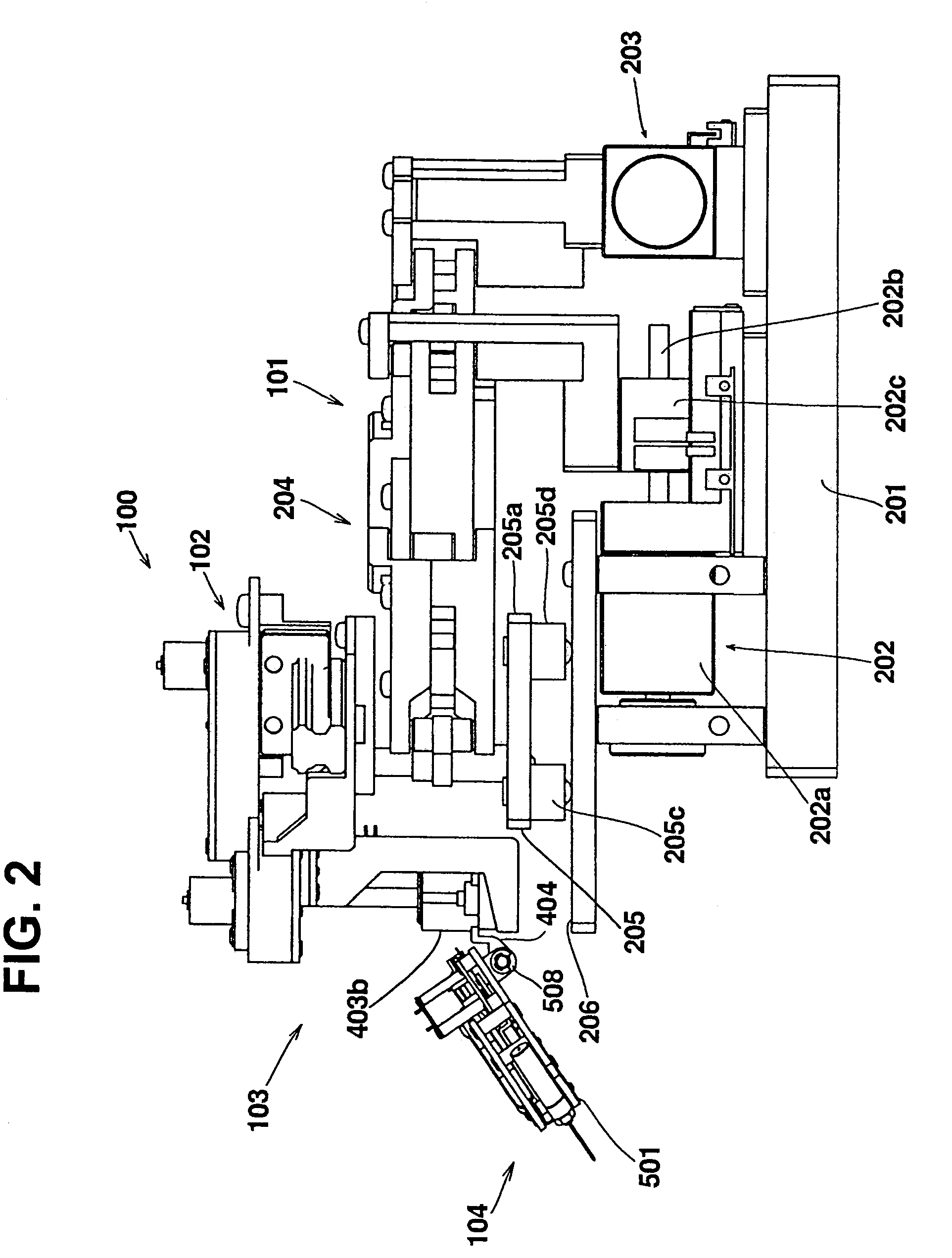
[0033]As shown in FIG. 1, the micro-material handling system 200 of the present embodiment has a micro-manipulator 100 for handling micro-material mounted on plate-shaped base 1 via a stand 4; a stage 3 for placing the micro-material to be handled by the micro-manipulator 100; a microscope 2, with a column thereof fastened to the plate-shaped base 1, and mounted with a CCD camera 5; a personal computer (hereinafter referred to as a PC) 6, and a control box 8 embedded with a programmable logic controller (hereinafter referred to as a PLC), for controlling the micro-manipulator 100 as a slave computer of the PC 6.

[0034]A cable for input and output with the control box 8, an output cable to a monitor 7 such as a liquid cryst...


PUM


Abstract

A micro-manipulator has a handling mechanism for gripping micro-material with two gripping fingers. The handling mechanism has a fixed finger with an end effecter for touching the micro-material, a movable finger with an end effecter capable of rotating around a rocking shaft for touching the micro-material, and an actuator for rotating the movable finger. The actuator drive moves the movable finger so as to be capable of touching a leading end of the movable finger end effecter to a leading end of the fixed finger end effecter. The micro-manipulator can securely and quickly grip a micro-material in a microscope visual field.

Description

CROSS-REFERENCE TO RELATED APPLICATION[0001]The application claims the priority of Japanese Patent Application No. 2005-23983 filed on Jan. 31, 2005, the disclosure of which is incorporated herein as a reference.BACKGROUND OF THE INVENTION AND RELATED ART STATEMENT[0002]The present invention relates to a micro-manipulator, and particularly to a micro-manipulator provided with a handling mechanism for gripping a micro-material with two gripping fingers.[0003]Conventionally, a micro-manipulator is used for assembling a micro-component and handling a cell. Generally, in order to grip a micro-material, a micro-manipulator has a mechanism for driving (handling mechanism) gripping fingers for handling the micro-material. (See Japanese Patent Publication Kokai No. 08-168979.) Working via a micro-manipulator generally requires viewing the micro-material through a microscope with the naked eye, or viewing an image output to a display via a CCD camera mounted on a microscope. (See Japanese Pa...

Claims


Application Information

Patent Timeline
Patent Type & Authority Patents(United States)
IPC IPC(8): B66C1/00B25J7/00B66C1/42
CPCG02B21/32
Inventor MOCHIZUKI, NAOTOYODA, YOSHIMICHI
Owner NISCA KK
Why Eureka
Try Eureka