
Display element drive unit, display device including the same, and display element drive method

a technology of display element and drive unit, which is applied in the direction of static indicating device, non-linear optics, instruments, etc., can solve the problems of instantaneous unexpected display, unstable voltage addition to source voltage, etc., and achieve the effect of minimizing the increase of the circuit scal

Inactive Publication Date: 2009-12-15
SHARP KK
View PDF26 Cites 5 Cited by
  • Summary
  • Abstract
  • Description
  • Claims
  • Application Information

AI Technical Summary

Benefits of technology

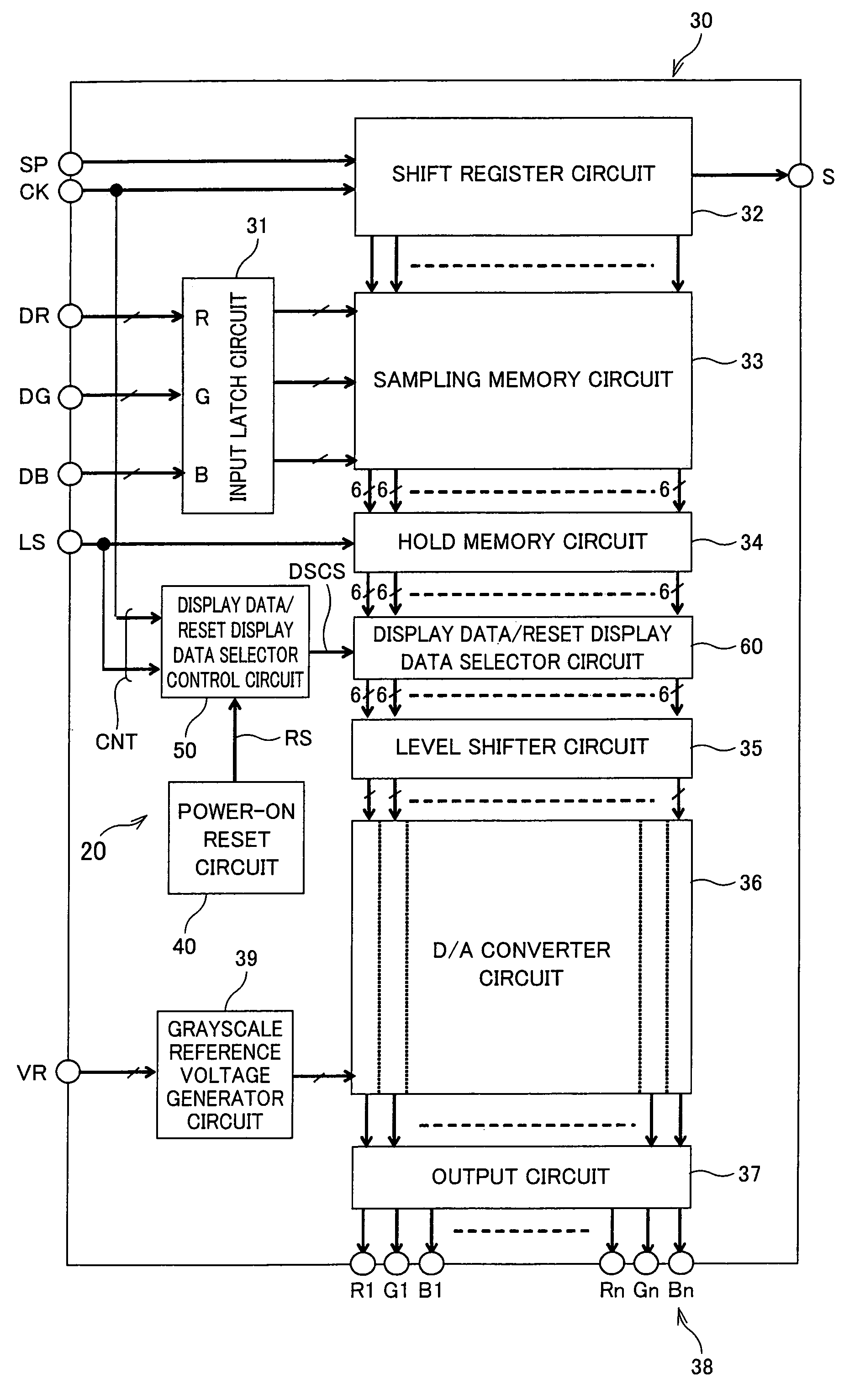
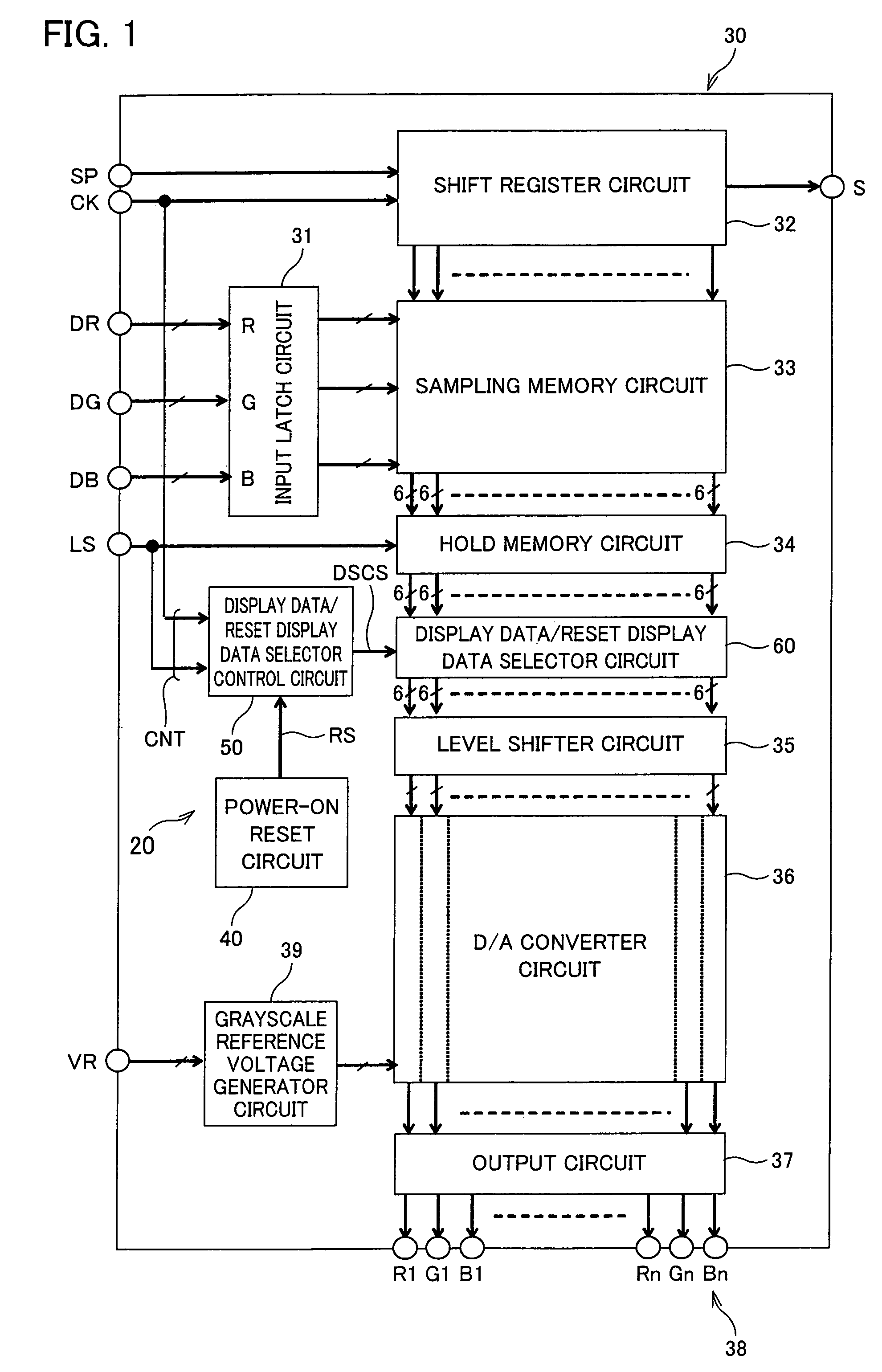
The present invention provides a display element drive unit, method, and display device that can prevent distorted images during power-on of a display panel. This is achieved by separately presetting and outputting grayscale display digital data during a given period of power-on, while minimizing circuit scale and terminals count. The power-on time display section includes a power-on time judgment section, a switch section, and a switch control section to switch between the separately preset grayscale display digital data based on the incoming display data signal. The arrangement of the power-on time display section is the same as the existing periphery components of the panel, making it easy to install. The digital-analogue converter section carries out digital-analogue conversion using a grayscale display reference voltage generator circuit and an adjustment amplifier, reducing circuit scale and terminals count.

Problems solved by technology

That is, due to gate voltage levels of the display element on the display panel, unstable voltages are added to the source voltages.
This might cause instantaneous unexpected displays on part of the scanning lines or over the entire display panel.

Method used


Image

  • Display element drive unit, display device including the same, and display element drive method
  • Display element drive unit, display device including the same, and display element drive method
  • Display element drive unit, display device including the same, and display element drive method

Examples


Embodiment Construction

[0063]The following will describe one embodiment of the present invention with reference to FIGS. 1 through 12.

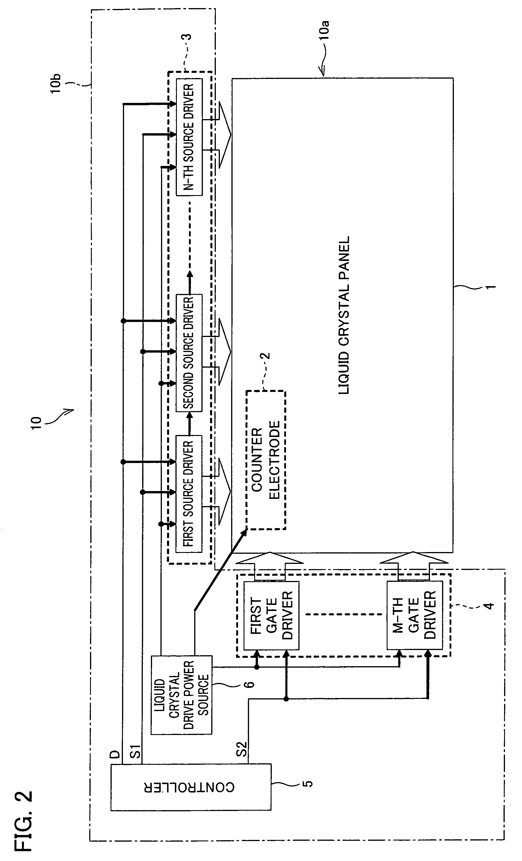
[0064]As illustrated in FIG. 2, a liquid crystal display device 10 as an active-matrix display device of the present embodiment is broadly divided into a liquid crystal display section 10a and a liquid crystal drive circuit 10b serving as a display element drive unit which drives the liquid crystal display section 10a.

[0065]The liquid crystal display section 10a has a liquid crystal panel 1 as a TFT display panel. The liquid crystal drive circuit 10b includes a source driver 3 and a gate driver 4 each of which is realized by IC (Integrated Circuit; semiconductor integrated circuit), a controller 5, and a liquid crystal drive power source 6.

[0066]In the liquid crystal display device 10 of the above arrangement, externally supplied display data is supplied as display data D, which is a digital signal, through the controller 5 to the source driver 3. The source driver 3 latch...


PUM


Abstract

A display element drive unit is provided with a power-on time display section which separately presets grayscale display digital data to output a grayscale display level voltage different from a grayscale display level voltage based on incoming display data signal to the display elements during a given period between power-on of the display panel and output of the grayscale display level voltage based on the incoming display data signal. With this arrangement, the present invention provides a display element drive unit capable of easing an instantaneous display of distorted image that occurs in a given period at power-on of the panel while minimizing increase of a circuit scale; a display device including the display element drive unit; and a display element drive method.

Description

[0001]This Nonprovisional application claims priority under 35 U.S.C. § 119(a) on Patent Application No. 291888 / 2004 filed in Japan on Oct. 4, 2004, the entire contents of which are hereby incorporated by reference.FIELD OF THE INVENTION[0002]The present invention relates to a display element drive unit which drives a plurality of display elements such as liquid crystal display elements, a display device including the display element drive unit, and a display element drive method. Examples of the display device include: an active-matrix liquid crystal display device; an electrophoretic display; a twist ball display; a reflective display using a fine prism film; a display using light modulation device such as a digital mirror device; a display using an element having a variable luminance of light, such as organic light-emitting display, inorganic light-emitting display, LED (Light Emitting Diode); a field emission display (FED); and a plasma display.BACKGROUND OF THE INVENTION[0003]A...

Claims


Application Information

Patent Timeline
Patent Type & Authority Patents(United States)
IPC IPC(8): G09G3/36
CPCG09G3/3648G09G3/3688G09G2320/0276G09G2310/027G09G2310/0245G09G3/36G02F1/133
Inventor SAKAGUCHI, NOBUHISA
Owner SHARP KK
Learn More