
Electro-optical device, driving circuit of electro-optical device, and electronic apparatus

a technology of electrooptical devices and driving circuits, applied in instruments, pisciculture and aquaria, computing, etc., can solve problems such as ghosting along gray-scale levels, predetermined voltages cannot be applied to each of the data lines, and delay of gray-scale signals with respect to sampling periods

Inactive Publication Date: 2009-12-15
SEIKO EPSON CORP
View PDF15 Cites 0 Cited by
  • Summary
  • Abstract
  • Description
  • Claims
  • Application Information

AI Technical Summary

Benefits of technology

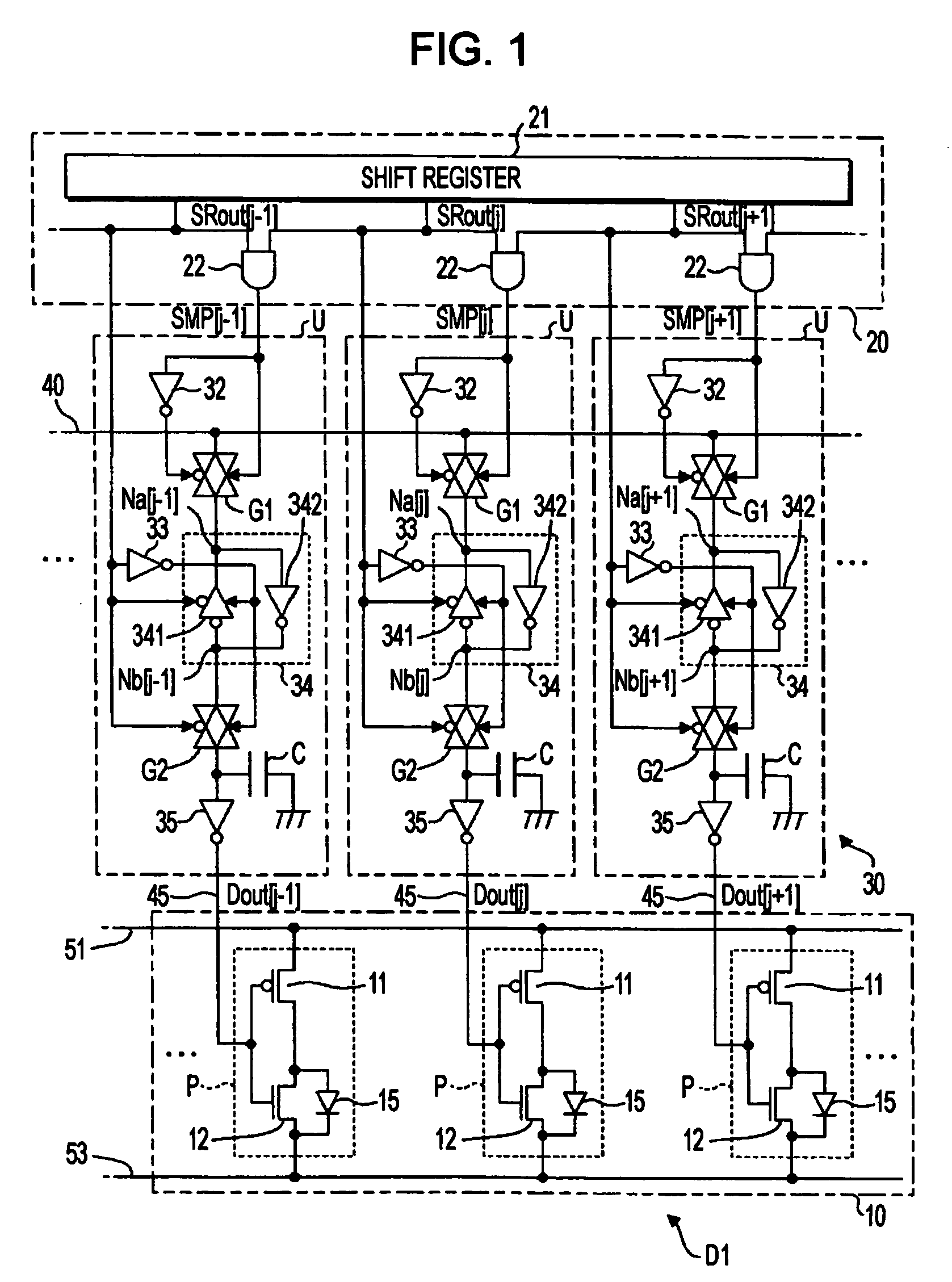
The invention provides an electro-optical device that prevents ghosting (the appearance of a ghost image) while also reducing the delay in the sampling of the gray-scale signal. This is achieved by a driving circuit that includes a pulse output circuit that outputs a plurality of sampling pulses, a plurality of unit circuits that are supplied with a sampling pulse and a signal line that is supplied with a gray-scale signal to sequentially designate a gray-scale level of each electro-optical element. The second switching element of each unit circuit is turned off for a predetermined period of time to prevent voltage errors in the data line. The electro-optical device includes an output buffer that holds a voltage for a predetermined period of time to ensure high precision in applying the gray-scale signal to the data line. The driving circuit and electro-optical device can be used in various electronic apparatuses such as inorganic EL diode elements, light-emitting diodes, liquid crystal elements, and OLED elements.

Problems solved by technology

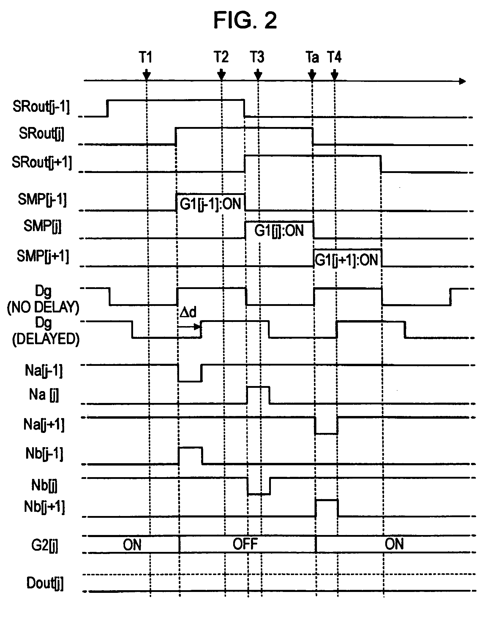
However, the gray-scale signal may be delayed with respect to the sampling period because of various factors such as a blunt waveform and a voltage drop in the signal line.
In this case, since a level of the gray-scale signal varies within one sampling period, the predetermined voltage cannot be applied to each of the data lines.
As a result, there is a problem in that irregularity of a gray-scale level (that is, a ghost) occurs along each of the data lines.
However, according to the above-mentioned technologies, the time length in which the gray-scale signal is sampled to the data line must be reduced by the gap D. Accordingly, in a case in which the gray-scale signal should be supplied to each of the data lines with a short cycle (for example, in a case in which the total number of the data lines is large), the sufficient gray-scale signal cannot be supplied to each of the data lines, so that it is difficult to control a gray-scale level of each electro-optical element with high precision.

Method used


Image

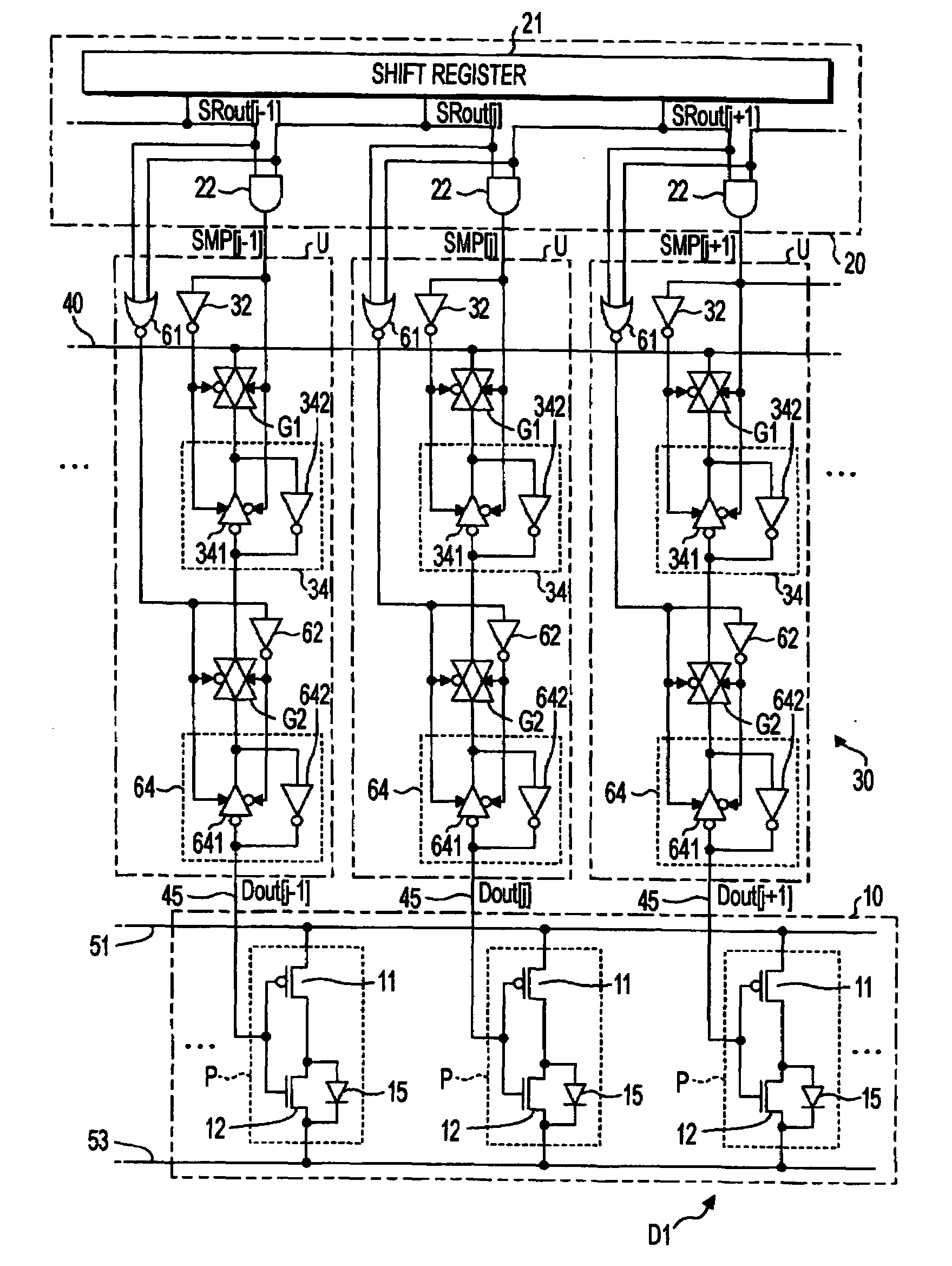
  • Electro-optical device, driving circuit of electro-optical device, and electronic apparatus
  • Electro-optical device, driving circuit of electro-optical device, and electronic apparatus
  • Electro-optical device, driving circuit of electro-optical device, and electronic apparatus

Examples


first embodiment

Modification of First Embodiment

[0058]Next, various modified aspects of the first embodiment will be described. Further, the various aspects of the first embodiment described below may be suitably combined. Hereinafter, in the various aspects, the same constituent elements as the first embodiment will be denoted by the same reference numerals as FIG. 1 and the description thereof will be omitted.

First Aspect

[0059]FIG. 5 is a circuit diagram showing a structure of the electro-optical device D1 according to the first aspect obtained by modifying the first embodiment. In FIG. 1, one end of the capacitor C is connected to a ground, but in the electro-optical device D1 according to the present aspect, one end of the capacitor C is connected to wiring lines including a wiring line to which a higher potential of a power supply Vdd is supplied (hereinafter, referred to as ‘higher power supply line’) and a wiring line to which a lower potential of a power supply Vss is supplied (hereinafter,...

second embodiment

Modification of Second Embodiment

[0071]Next, various modified aspects of the second embodiment will be described. Further, the various aspects of the second embodiment described below may be suitably combined. Hereinafter, in the various aspects, the same constituent elements as the first embodiment and the second embodiment will be described by the same reference numerals as FIGS. 1 and 10 and the description thereof will be omitted.

First Aspect

[0072]In FIG. 10, the voltage Dout of the data line 45 is held by only the gate capacitor Cg. However, one end of the same capacitor C as the first embodiment may be connected to the output terminal of the clocked inverter 38. The structure shown in FIG. 5 or 6 may be applied to the present embodiment. For example, as shown in FIG. 11, a structure may be used in which one end of the capacitor C is connected to a wring line for connecting a higher power supply line supplied with the higher potential of the power supply Vdd and a lower power s...


PUM


Abstract

A driving circuit drives an electro-optical device in which a gray-scale level of each of a plurality of electro-optical elements provided so as to correspond to a plurality of data lines is controlled on the basis of a voltage of a corresponding data line. The driving circuit includes a pulse output circuit that outputs a plurality of sampling pulses, each of the plurality of sampling pulses becoming an active level sequentially; a plurality of unit circuits each of which is supplied with a sampling pulse from the pulse output circuit; and a signal line that is supplied with a gray-scale signal to sequentially designate a gray-scale level of each of the electro-optical elements. Each of the plurality of unit circuits has a first switching element that samples the gray-scale signal supplied to the signal line in accordance with a sampling pulse output from the pulse output circuit; a second switching element that is inserted between the first switching element and the data line and enters an off state until a predetermined period passes from a time when sampling operation is started by the first switching element; and a storage capacitor that holds a voltage of an output terminal of the second switching element.

Description

CROSS-REFERENCE TO RELATED APPLICATION[0001]The present application claims priority to Japanese Patent Application No. 2005-011181 filed Jan. 19, 2005, which is hereby expressly incorporated by reference herein its entirety.BACKGROUND[0002]1. Technical Field[0003]The present invention relates to a technology for controlling an electro-optical element such as an organic light-emitting diode (OLED) element or the like.[0004]2. Related Art[0005]Generally, electro-optical devices with a plurality of electro-optical elements have been widely used. Each of the plurality of electro-optical elements is disposed so as to correspond to any one of a plurality of data lines, and a gray-scale level of each electro-optical element is controlled on the basis of a voltage applied to the corresponding data line. Each of the data lines is commonly connected to a signal line through a switching element disposed so as to correspond to the data line. This signal line is supplied with a gray-scale signal...

Claims


Application Information

Patent Timeline
Patent Type & Authority Patents(United States)
IPC IPC(8): G09G3/36
CPCG09G3/3258G09G3/3291G09G2320/0257A01K61/51A01K61/30
Inventor KUBOTA, TAKEHIKOFUJIKAWA, SHINSUKE
Owner SEIKO EPSON CORP
Learn More