Fringe field switching LCD having smectic liquid crystal and utilizing alternate current squared wave driving voltage

a technology driving voltage, which is applied in the field of lcd panels, can solve the problems of easy non-self-repairing alignment defect of liquid crystal molecule of smectic liquid crystal layer, and reducing the contrast of flc monitors, so as to improve the contrast of lcd monitors and arrays smooth

Active Publication Date: 2009-12-15
AU OPTRONICS CORP
View PDF33 Cites 4 Cited by
  • Summary
  • Abstract
  • Description
  • Claims
  • Application Information

AI Technical Summary

Benefits of technology

[0009]The invention provides an LCD panel whose design of having a polymer network be disposed inside the smectic liquid crystal layer can adjust the liquid crystal molecule of the smectic liquid crystal layer to achieve a smooth array and alignment and prevent the liquid crystal molecule of the smectic liquid crystal layer from the zigzag wall alignment defect, lest light leakage might occur to the LCD monitor due to the zigzag wall alignment defect, largely improving the contrast of the LCD monitor. Furthermore, the LCD panel of the invention, by inter-spacing the positive and the negative electrodes on the same substrate, simultaneously generates the positive and the negative electrical fields perpendicular to the substrate surface, achieving the function of multiple domains and horizontal rotation. Besides, the LCD panel of the invention whose design of controlling the penetration rate of LCD monitor according to the height or width of the driving alternate current (AC) squared wave can be fit into the manufacturing technology of LCD monitors without using any conventional grey level display methods such as the pixel area dividing method, the frame time dividing method or the driving voltage dividing method. Therefore, the problems associated with the application of conventional grey level display methods such as the pixel area dividing method, the frame time dividing method or the driving voltage dividing method can be avoided.

Problems solved by technology

In a conventional ferroelectric liquid crystal (FLC) monitor, the alignment of the smectic liquid crystal layer is achieved through the rubbing method, causing the liquid crystal molecule of the smectic liquid crystal layer to have the zigzag wall alignment defect easily.
Consequently, the FLC monitor would have light leakage due to the zigzag wall alignment defect, decreasing the contrast of the FLC monitor.
Furthermore, the alignment defect generated in the liquid crystal molecule of the smectic liquid crystal layer is not self-repairing.
An ordinary user would not be able to eliminate the alignment defect occurring to the liquid crystal molecule due to the mechanical deformation of the FLC monitor, largely affecting the acceptability of FLC monitor by the user.
Therefore, the design of the cell gap between the top and the bottom substrates and the embossing design on the surface of the substrate are tougher and the manufacturing process is more difficult accordingly.
The disadvantage for pixel area dividing method is that the more sub-pixels are divided, the lower the yield rate.
The disadvantage for frame time dividing method is that a high speed driving circuit is required when dividing the grey level.
The disadvantage for driving voltage dividing method is that since the display having optical and electrical bistable characteristics is driven according to the volume of the voltage, both voltage squared wave and the driving circuit become very complicated.

Method used


Image

  • Fringe field switching LCD having smectic liquid crystal and utilizing alternate current squared wave driving voltage
  • Fringe field switching LCD having smectic liquid crystal and utilizing alternate current squared wave driving voltage
  • Fringe field switching LCD having smectic liquid crystal and utilizing alternate current squared wave driving voltage

Examples


first embodiment

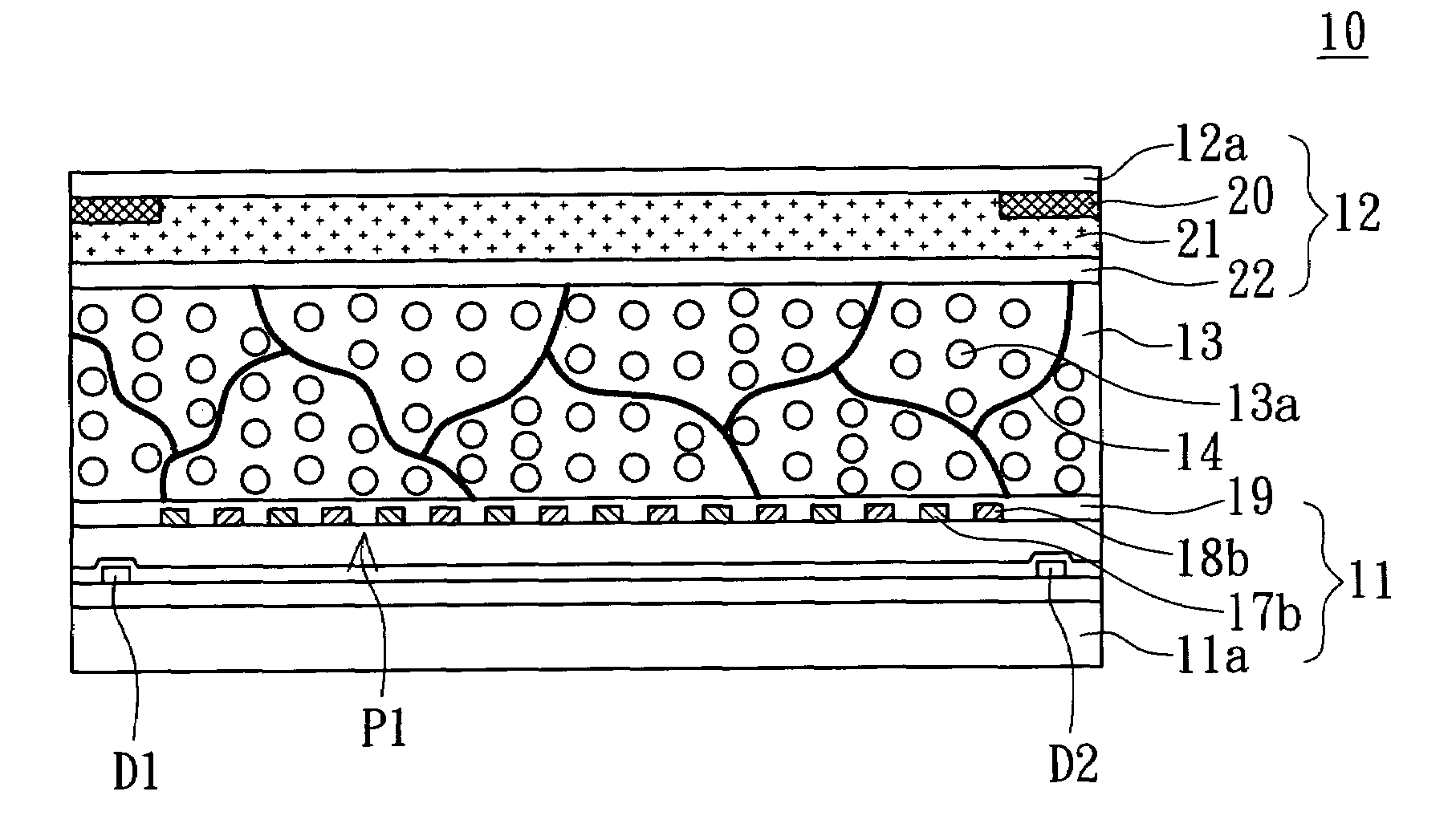
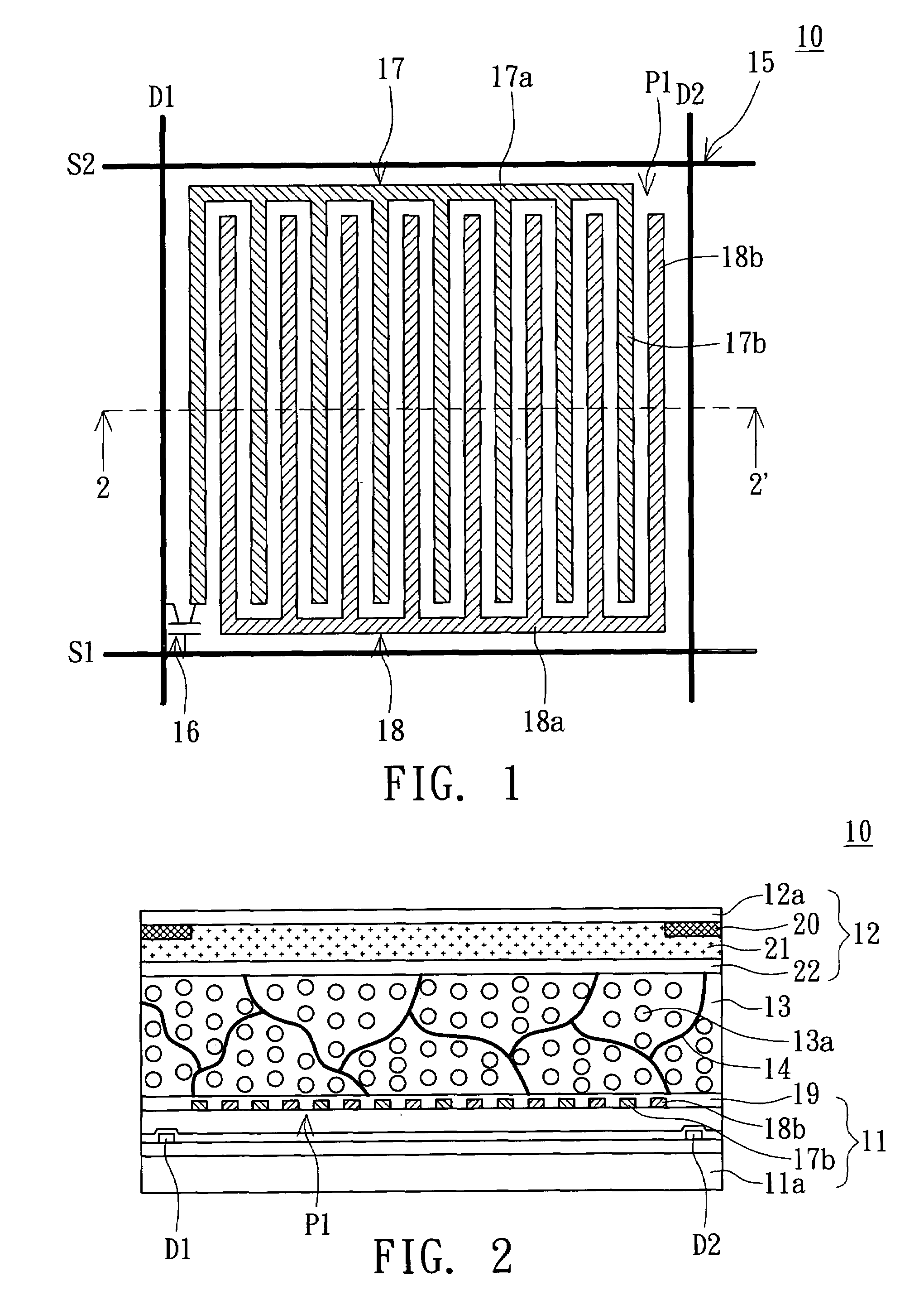
[0022]Referring to both FIGS. 1˜2, FIG. 1 is a top view of the circuit structure of an LCD panel according to a first embodiment of the invention, while FIG. 2 is an enlarged view of a partial cross-sectional structure of the LCD panel viewed along the cross-sectional line 2-2′ of FIG. 1. In FIGS. 1˜2, the LCD panel 10 includes a first substrate 11, a second substrate 12, a smectic liquid crystal layer 13 and a polymer network 14.

[0023]the first substrate 11 includes a first base 11a, an active matrix pixel array 15, at least a control switch, a first electrode 17, a second electrode 18 and a first horizontal alignment film 19. The active matrix pixel array 15 is disposed on the first base 11a and includes a number of pixels. Each pixel is defined by two adjacent scan lines or gate lines and two adjacent data lines or source lines. The two adjacent scan lines or gate lines and the two adjacent data lines or source lines are inter-spaced to be disposed on the first base 11a. In the p...

second embodiment

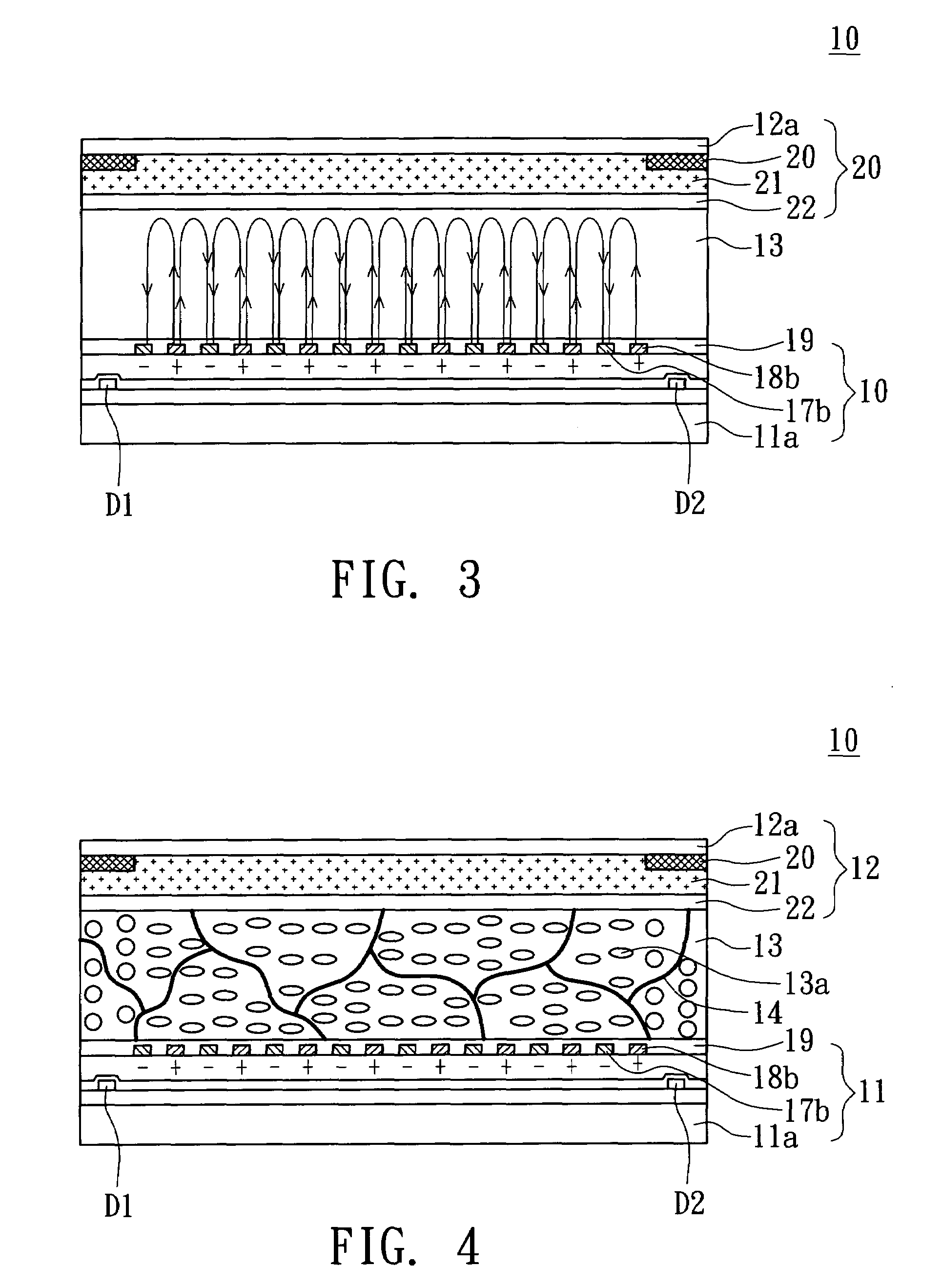
[0037]Referring to FIG. 7, a diagram showing partial cross-sectional structure of the LCD monitor according to a second embodiment of the invention is shown. In FIG. 7, LCD monitor 30 includes a backlight module 31, a first polarizer 32, a second polarizer 33 and an LCD panel 10 disclosed in the first embodiment. The first polarizer 32 is disposed on the backlight module 31. The LCD panel 10 is disposed on the first polarizer 32. The second polarizer 33 is disposed on the LCD panel 10. The light penetration axis of the first polarizer 32 is substantially perpendicular to that of the second polarizer 33. The first polarizer 32 and the second polarizer 33 are respectively adjacent to the first substrate 11 and the second substrate 12.

[0038]When the LCD monitor 30 displays a frame at a frequency within the time interval from 60 Hz to 1 kHz, the wave pattern of the driving voltage of the first electrode 17 and the second electrode 18 can be a squared wave alternating among positive volt...


PUM

PropertyMeasurementUnit
thicknessaaaaaaaaaa
frequencyaaaaaaaaaa
electrical fieldaaaaaaaaaa

Abstract

An LCD panel including a first substrate, a second substrate and a smectic liquid crystal layer is disclosed. The first substrate includes a first electrode, a second electrode and a first horizontal alignment film. The first electrode has plural first portions. The second electrode has plural second portions. The first portions are spaced by the second portions. The electrical field directions formed between the first portions and the second portions are perpendicular to the surface of the first substrate. The electrical field direction on each first portion is opposite to that on each second portion. The first horizontal alignment film covers the first and the second electrodes. The second substrate includes a second horizontal alignment film. The horizontal rubbing direction of the first horizontal alignment film is parallel to that of the second horizontal alignment film. The smectic liquid crystal layer is sealed between the first and the second substrates.

Description

[0001]This application claims the benefit of Taiwan Application Serial No. 94113952, filed on Apr. 29, 2005, the subject matter of which is incorporated herein by reference.BACKGROUND OF THE INVENTION[0002]1. Field of the Invention[0003]The invention relates in general to an LCD panel, and more particularly to a smectic liquid crystal layer capable of turning horizontally to form an LCD panel with multiple domains according to the opposite but perpendicular electrical field directions between adjacent electrodes.[0004]2. Description of the Related Art[0005]In a conventional ferroelectric liquid crystal (FLC) monitor, the alignment of the smectic liquid crystal layer is achieved through the rubbing method, causing the liquid crystal molecule of the smectic liquid crystal layer to have the zigzag wall alignment defect easily. Consequently, the FLC monitor would have light leakage due to the zigzag wall alignment defect, decreasing the contrast of the FLC monitor.[0006]Furthermore, the...

Claims


Application Information

Patent Timeline
Patent Type & Authority Patents(United States)
IPC IPC(8): G02F1/1343G09G3/36
CPCG02F1/141G02F2001/13775G02F2001/134381G02F1/134381G02F1/13775
Inventor LIN, TZU-YUANHUANG, REN-HUNGWU, PO-CHANGTSAY, SHWU-YUNWU, SHUNE-LONGSUN, CHIA-HSINGWU, JIN-JEICHEN, PO-LUNLIU, AI-SEN
Owner AU OPTRONICS CORP
Why Eureka
Try Eureka