Failure recovery method
a technology of failure recovery and recovery method, applied in the field of failure recovery, can solve the problem that the failed server cannot be correctly taken over to a spare server, and achieve the effect of saving software licensing fees, reducing the number of spare servers, and improving reliability
- Summary
- Abstract
- Description
- Claims
- Application Information
AI Technical Summary
Benefits of technology
Problems solved by technology
Method used
Image
Examples
first embodiment
1. First Embodiment
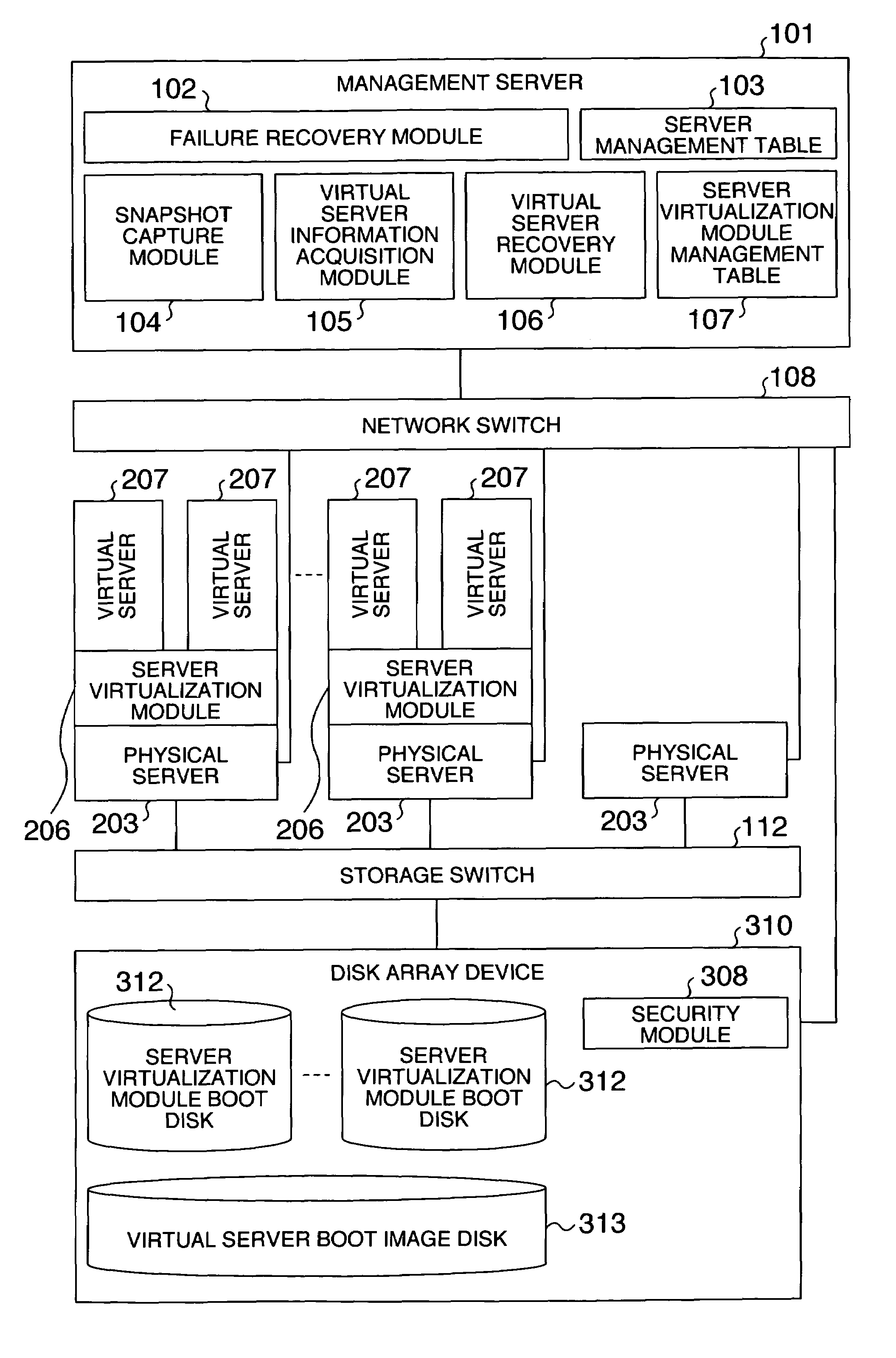
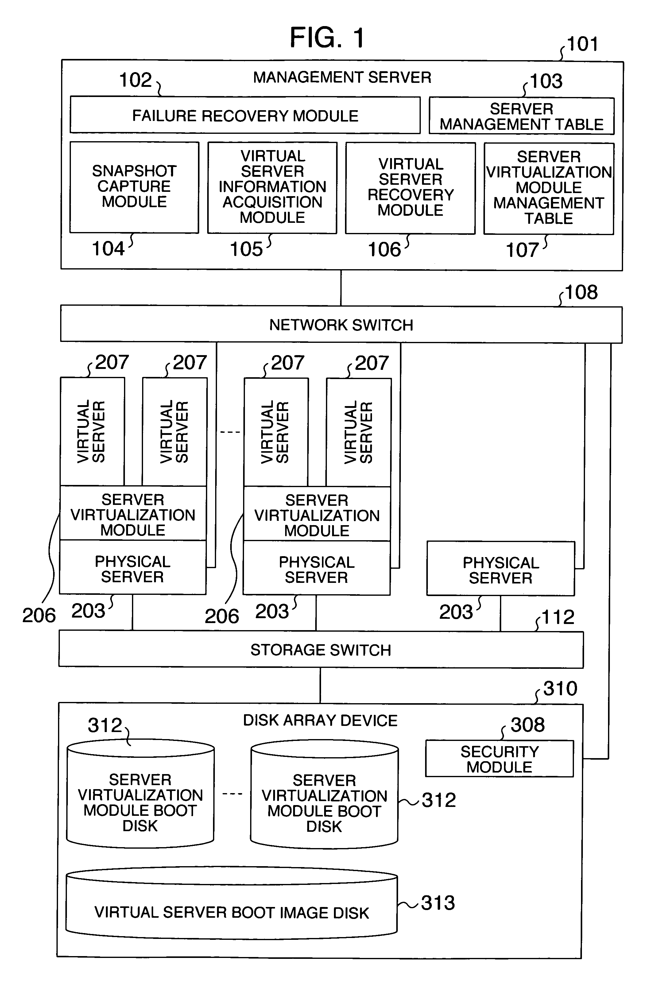
[0032]FIG. 1 generally illustrates a virtual server environment which embodies a failure recovery method according to a first embodiment in the present invention. Control operations characteristic of this embodiment are conducted mainly by a management server 101. The management server 101 comprises a failure recovery module 102, a snapshot capture module 104, a virtual server information acquisition module 105, a virtual server recovery module 106, a server management table 103, and a server virtualization module management table 107. The management server 101 manages a network switch 108, a plurality of physical servers 203, a disk array device 310, and a server virtualization module 206 provided in each physical server. Here, the server virtualization module 206 has a function of making the physical server 203 look like a plurality of virtual servers. In other words, a plurality of virtual servers can be integrated into the single physical server 203. The disk ...
second embodiment
2. Second Embodiment
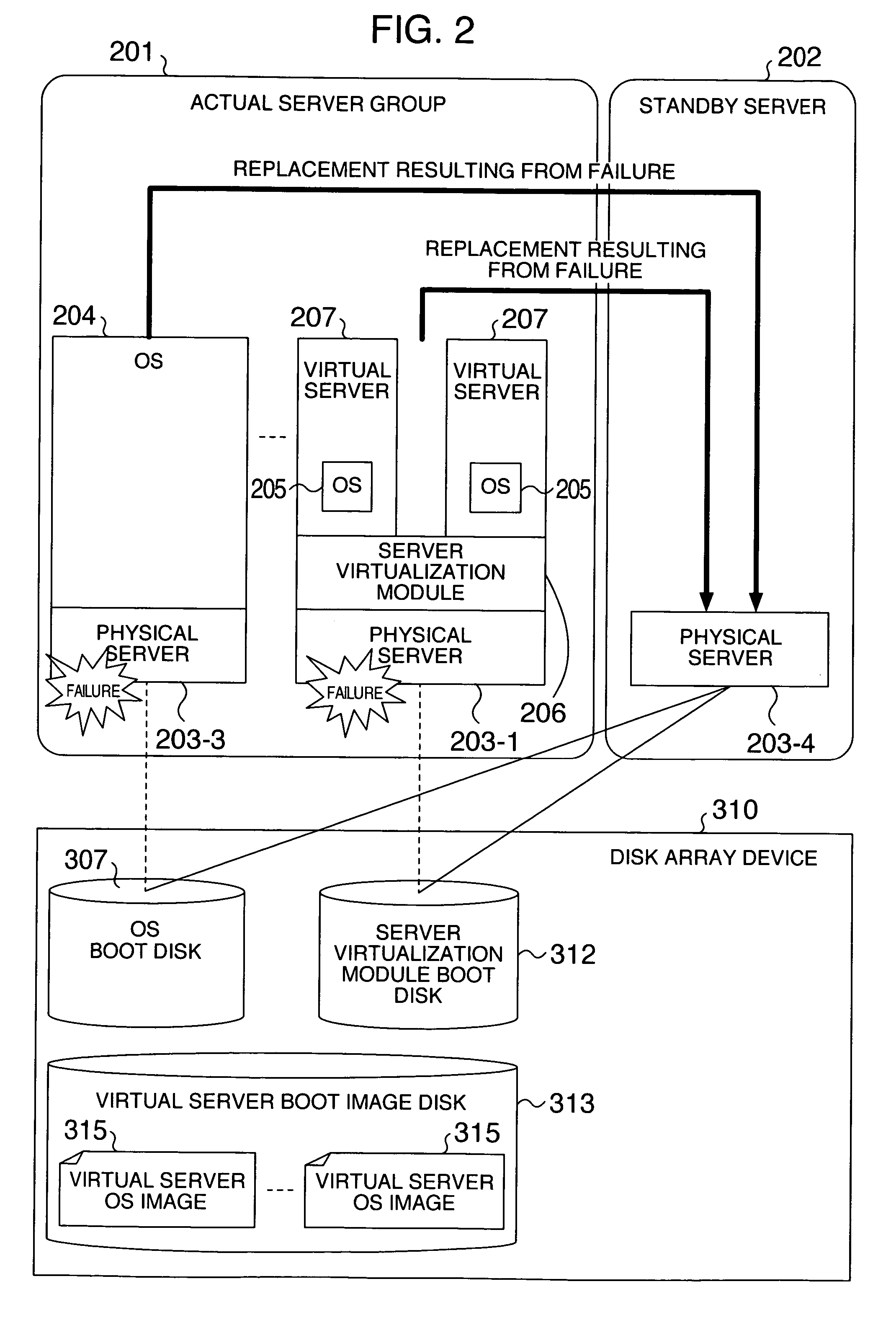
[0043]FIG. 13 generally illustrates a virtual server environment which embodies a failure recovery method according to a second embodiment in the present invention. The second embodiment mainly differs from the first embodiment in that the former comprises a failure recovery module 1301 and a virtual server recovery module 1302 in a management server 151. In the first embodiment, a failed one of the active physical servers 203 is replaced by a physical server in the standby system. In the second embodiment, even if failures have occurred in a plurality of physical servers with server virtualization modules being active on the respective ones, the physical servers can be recovered by a single physical server in a standby system.
[0044]FIG. 14 generally illustrates operations involved in the failure recovery method according to the second embodiment. Server virtualization modules 206-1, 206-2 are active respectively on a plurality of servers 203-1, 203-2 which make ...
third embodiment
3. Third Embodiment
[0047]A third embodiment of the present invention provides a system which can recover a failed physical server that has a server virtualization module as well as a failed physical server that does not have a server virtualization module by a single physical server in a standby system, irrespective of which physical server fails earlier.
[0048]The general system configuration of the third embodiment is similar to the configuration of the system in the first embodiment illustrated in FIG. 1. Also, the physical server 203 of the third embodiment is not either different from that illustrated in FIG. 3. FIG. 17 is a block diagram generally illustrating operations performed in the configuration of the third embodiment.
[0049]A server virtualization module 206-6 has been previously provided for a physical server 203-6 in a standby system 202. A server virtualization module boot disk 312-6 is used to previously activate the server virtualization module 206-6. An OS 204 whic...
PUM
 Abstract
Description
Claims
Application Information
 - R&D
- Intellectual Property
- Life Sciences
- Materials
- Tech Scout
- Unparalleled Data Quality
- Higher Quality Content
- 60% Fewer Hallucinations
Browse by: Latest US Patents, China's latest patents, Technical Efficacy Thesaurus, Application Domain, Technology Topic, Popular Technical Reports.
© 2025 PatSnap. All rights reserved.Legal|Privacy policy|Modern Slavery Act Transparency Statement|Sitemap|About US| Contact US: help@patsnap.com


