Cable protection and guide device

a technology of guide device and cable, which is applied in the direction of machine supports, other domestic objects, mechanical apparatus, etc., can solve the problems of excessive bending fatigue in the coupling b>513/b>, and achieve the effects of reducing bending fatigue, reducing tensile stress in the coupling arm, and improving enduran

Active Publication Date: 2009-12-29
TSUBAKIMOTO CHAIN CO
View PDF10 Cites 9 Cited by
  • Summary
  • Abstract
  • Description
  • Claims
  • Application Information

AI Technical Summary

Benefits of technology

[0015]According to the cable or like protection and guide device of the present invention: a number of pairs of spaced right and left side plate portions are connected to each other from a mounting fixed end to a mounting movable end; connecting arms axe respectively bridged over a bending inner circumferential side and a bending outer circumferential side of the side plate portions at predetermined intervals; and, the cable is accommodated and guided in a cable accommodating space surrounded by the side plate portions and the connecting arms from a mounting fixed end toward a mounting movable end so that the cable protection and guide device can assume a linear position and / or a bending position. Additionally the following significant effects are obtained by the configurations of the present invention.
[0016]The cable protection and guide device of the present invention includes: integrally molded side plate portions and coupling portions which form a connecting link module; a stopper link, which holds and limits the linear position and the bending position by engagement with the connecting link module, and, the stopper link is inter-fitted with the coupling portion of the connecting link module by a snap-fit mechanism from the cable accommodating space side. Thus, the number of parts and attendant assembly thereof is reduced.
[0017]The connecting link module is incorporated to a stopper link by the snap-fit mechanism and the tensile stress applied to the coupling arm is dispersed through the snap-fit mechanism. Thus large tensile stresses in the coupling arm are reduced so that bending fatigue is suppressed and endurance is improved.
[0018]The connecting link module is formed of a polyamide fatigue resistant resin and the stopper link is formed of a polyacetal resin. The polyacetal resin of the stopper link exhibits high rigidity whereby a snap-fit mechanism, which exhibits large bonding strength during assembly of the device, can be formed. Further, since the polyamide fatigue resistant resin connecting link module and the polyacetal resin stopper link smoothly slide with respect to each other, the generation of dust such as wear powder is suppressed enabling to use of the device in a clean environment such as with foods and semiconductors.
[0019]The polyamide fatigue resistant resin contains a rubber component which significantly improves bending fatigue resistance of the connecting link module. Therefore, even if the connecting link module is repeatedly bent for a long period of time excellent endurance is exhibited.
[0020]The connecting arm is formed of a polyacetal resin. The stopper link and the connecting arm exhibit deflection rigidity and torsional rigidity during assembly. Therefore, a rectangular cross-sectional form of the cable accommodating space surrounded by connecting arms bridged over a pair of spaced right and left stopper links is ensured.

Problems solved by technology

Excessive bending fatigue in the coupling 513 is also known to be a problem.

Method used


Image

  • Cable protection and guide device
  • Cable protection and guide device
  • Cable protection and guide device

Examples


example 1

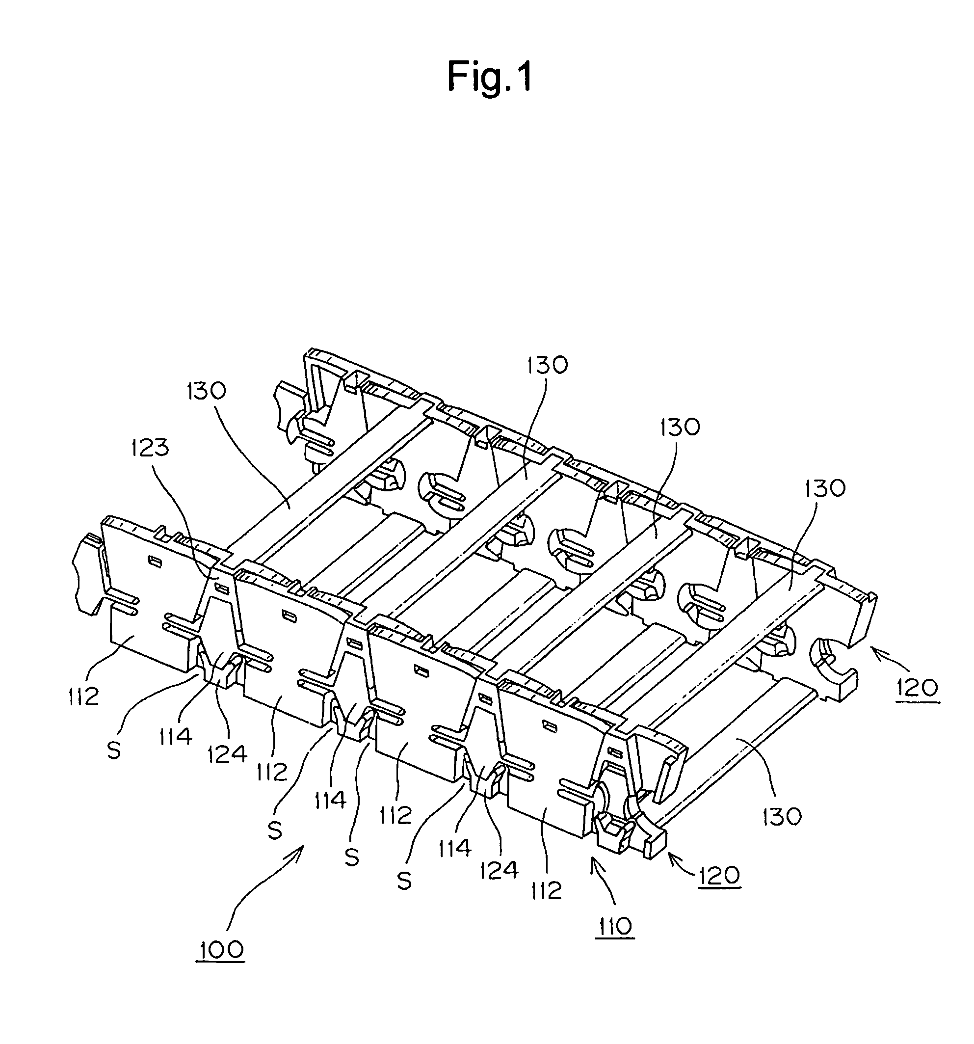
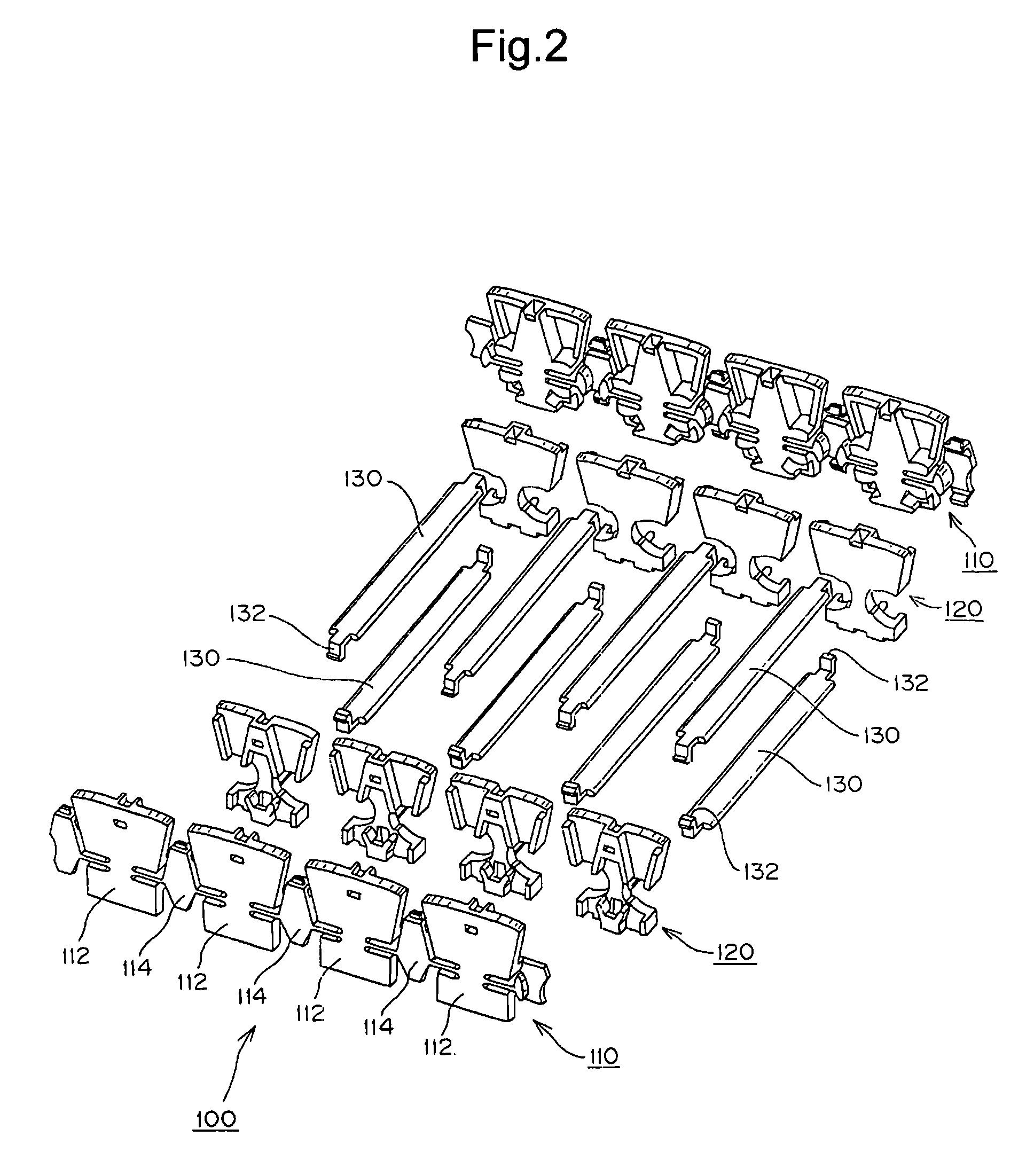
[0039]A cable protection and guide device 100, which is Example 1 of the present invention, will be described by use of FIGS. 1 to 6 hereinbelow.

[0040]FIG. 1 is a perspective view of a part of the cable protection and guide device 100, which is the present example. FIG. 2 is an exploded view of the cable protection and guide device 100 shown in FIG. 1. FIG. 3 is a perspective view of connecting link modules 110, which are components of the cable protection and guide device 100 shown in FIG. 1, and particularly FIG. 3(a) is a perspective view from the within of a cable accommodating space and FIG. 3(b) is a perspective view from the outside of it. FIG. 4 is a perspective view of a stopper link, which is a component of the cable protection and guide device 100 shown in FIG. 1, and particularly, FIG. 4(a) is a perspective view showing a side which is incorporated to the connecting link module, and FIG. 4(b) is a perspective view from the within of the cable accommodating space side.

[00...

example 2

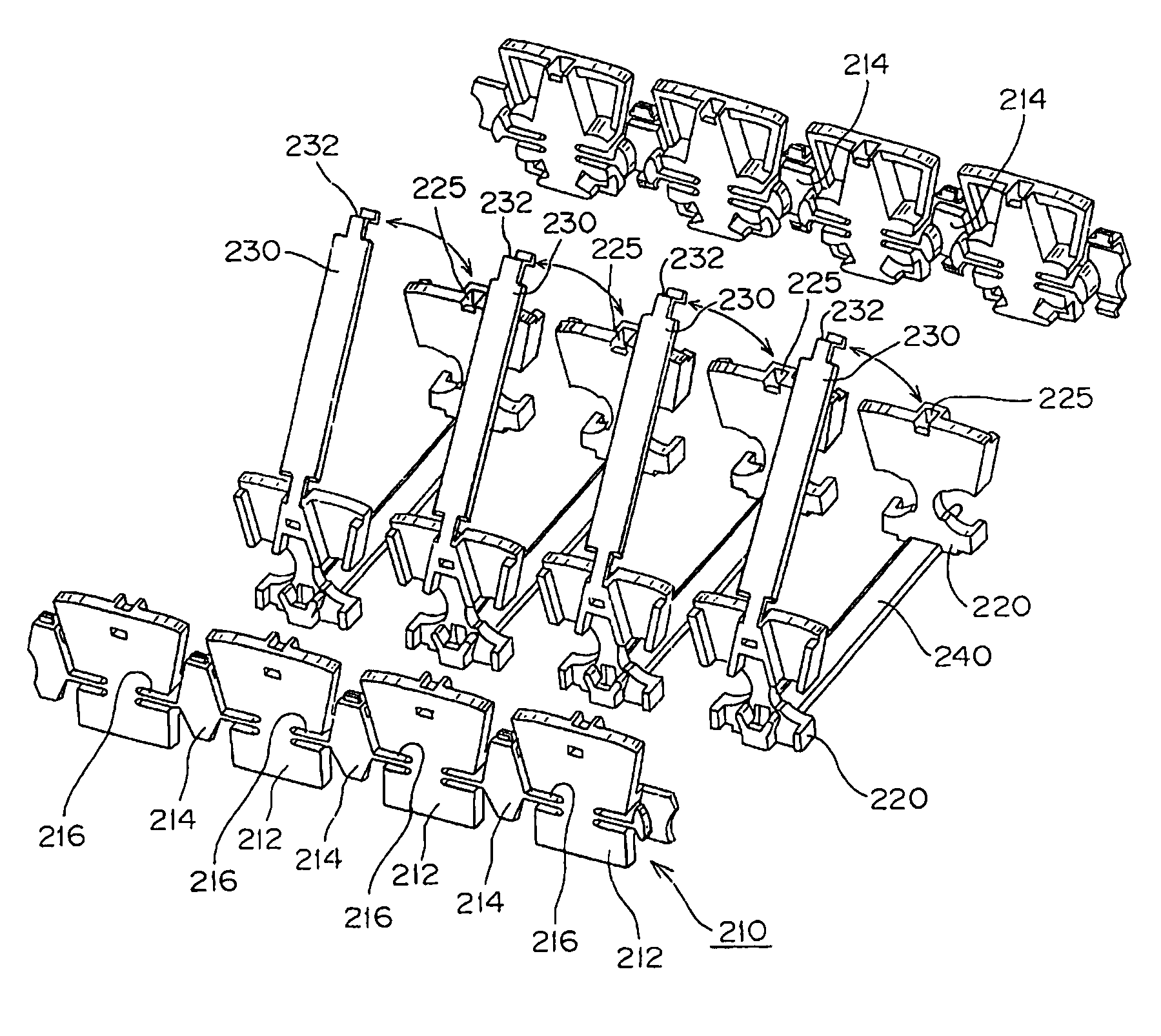
[0071]A cable protection and guide device 200 of Example 2, which is another embodiment of the present invention, will be described by use of FIGS. 7 and 8.

[0072]FIG. 7 is a perspective view of Example 2 showing a part of the cable protection and guide device 200. FIG. 8 is an exploded view of the cable protection and guide device 200 shown in FIG. 7.

[0073]In the cable protection and guide device 200, which is Example 2, as shown in FIGS. 7 and 8, a plurality of side plate portions 212 and coupling portions 214 are integrally molded and form a rubber component-containing polyamide fatigue resistance resin connecting link module 210.

[0074]The plurality of side plate portions 212 form an elongated connecting link module 210. Horizontally elongated coupling arms 216 are connected to substantially diamond-shaped coupling portions 214 formed between adjacent side plate portions 212, 212 as shown in FIG. 8.

[0075]And a polyacetal resin stopper link 220 is inter-fitted with a coupling porti...

example 3

[0081]A cable protection and guide device 300 of Example 3, which is still another embodiment of the present invention, will be described by use of FIGS. 9 and 10.

[0082]FIG. 9 is a perspective view showing a part of the cable protection and guide device 300, which is Example 3. FIG. 10 is an exploded view of the cable protection and guide device 300 shown in FIG. 9.

[0083]In the cable protection and guide device 300, which is Example 3, as shown in FIGS. 9 and 10, a plurality of side plate portions 312 and coupling portions 314 are integrally molded and form a connecting link module 310.

[0084]The plurality of side plate portions 312 form an elongated connecting link module 310. Horizontally elongated coupling arms 316 are connected to substantially diamond-shaped coupling portions 314 formed between adjacent side plate portions 312, 312 as shown in FIG. 10.

[0085]A polyacetal resin stopper link 320 is inter-fitted with a coupling portion 314 of the connecting link module 310 by a snap...


PUM

PropertyMeasurementUnit
energyaaaaaaaaaa
electric poweraaaaaaaaaa
movementaaaaaaaaaa

Abstract

A cable protection and guide device in which the number of parts used is reduced and assembly is simplified. Dust generation and bending fatigue is suppressed so that the cable protection and guide device exhibits excellent form stability of the cable accommodating space. Side plate portions and coupling portions are integrally molded from polyamide fatigue resistant resin into the form of a connecting link module. A polyacetal resin stopper link, which holds and limits the linear position and the bending position by engagement with the connecting link module, is inter-fitted with a coupling portion of the connecting link module by a snap-fit mechanism from the cable accommodating space side.

Description

[0001]This patent application claims priority to Japanese Patent Application 2008-115456 filed on Apr. 25, 2008.TECHNICAL FIELD[0002]The present invention relates to a cable protection and guide device. More specifically it relates to a cable protection and guide device which preferably accommodates a cable or a hose or multiple cables and hoses. The cable supplies the movable portion of an industrial machine with energy such as electric power or compressed air. The protection and guide device stably and reliably supports and guides the cable during movement of the movable portion.BACKGROUND TECHNOLOGY[0003]A conventional cable protection and guide device is shown in FIG. 11. A cable protection and guide device 500 is formed such that a number of pairs of spaced right and left side plate portions 510A and 510B are connected to each other from a mounting fixed end to a mounting movable end in a longitudinal direction. Connecting arms 520 are respectively bridged over a bending inner ...

Claims


Application Information

Patent Timeline
Patent Type & Authority Patents(United States)
IPC IPC(8): F16G13/16
CPCF16G13/16H02G3/0475Y10S59/90H02G11/006
Inventor UTAKI, AKIHIKOIKEDA, MASAAKI
Owner TSUBAKIMOTO CHAIN CO
Why Eureka
Try Eureka