
Filter element, especially for filtering the exhaust gases of an internal combustion engine

a filter element and internal combustion engine technology, applied in auxillary pretreatment, ceramicware, separation processes, etc., can solve the problems of large mechanical stress, increase in pressure drop, and decrease in permeability of filter walls, so as to achieve large tensile stress, easy to absorb, and reduce the effect of permeability

Inactive Publication Date: 2010-08-19
ROBERT BOSCH GMBH
View PDF28 Cites 7 Cited by
  • Summary
  • Abstract
  • Description
  • Claims
  • Application Information

AI Technical Summary

Benefits of technology

[0006]What is achieved with the geometry according to the present invention of the filter walls is that greater stresses can be absorbed in an outer region of the filter element without failure of the material in that region. The tensile forces occurring in an outer region of the filter element can best be absorbed when at least some of the filter walls of the inlet channels and outlet channels disposed in this region are adapted in terms of their profile to the profile of the curved outer side. With a conventional filter element, by contrast, the inlet channels and outlet channels are also offset in checkerboard fashion from one another in an outer region of the element, so that the inlet channels and outlet channels are cut off on the outer side in terms of their substantially square basic shape. These irregularly shaped externally located inlet channels and outlet channels form regions of material weakness that promote cracking.
[0007]The filter element according to the present invention can have a substantially cylindrical or oval cross section. In this case the entire outer side of the filter element has a curved profile. It is also possible, however, for the filter element to have an outer side that in cross section is alternately delimited by segments proceeding rectilinearly and segments proceeding in curved fashion. A cross section of this kind has a basic shape that is polygonal, for example triangular or square, in cross section. The edges of these polygons then form segment proceeding rectilinearly, between which (in the corner regions of the basic shape) are provided segments proceeding in curved fashion.
[0008]For the aforesaid cross sections, it is advantageous if the filter walls in a region adjacent to the curved outer side are concentric with one another. If some of the filter walls extend in a radial direction, it is thereby possible, with the aid of the filter walls disposed mutually concentrically and with the aid of the filter walls extending in a radial direction, to create inlet channels and outlet channels whose cross section deviates only slightly from a square or rectangular basic shape.
[0009]If the filter walls of a row of inlet channels and outlet channels that is directly adjacent to the outer side of the filter element are adapted to the profile of the outer side, the particularly large tensile stresses in this region in the context of regeneration of the filter element can be readily absorbed. It is thereby possible to prevent the formation, in this particularly at-risk region, of cracks that can then propagate into regions less at risk. This can be prevented particularly effectively if the filter walls of several mutually adjacent rows of inlet channels and outlet channels are adapted to the profile of the outer side. It is thereby also possible to avoid abrupt changes in geometry between a row of inlet channels and outlet channels that is located farthest out, and a row of inlet channels and outlet channels that is located internally relative thereto.
[0010]The outer region, i.e. the region in which the profile of some of the filter walls is adapted to the profile of the outer side, can extend from the outer side to between 0.1 and 0.4 times the greatest diameter of the filter element.
[0011]It is particularly advantageous if the outer region is contiguous to an inner region, polygonal overall in cross section, of the filter element. This polygonal region allows the provision of inlet channels and outlet channels having a conventional geometry, especially when the inner region has an overall cross section that is substantially quadrangular.

Problems solved by technology

These carbon particles result in a decrease in the permeability of the filter walls, and consequently in an increase in the pressure drop that occurs as the gas flow passes through the filter walls.
This leads to locally different thermal expansions, with the result that large mechanical stresses can occur in the filter element.
In the least favorable case, these stresses can cause cracks to form in the filter element.

Method used


Image

  • Filter element, especially for filtering the exhaust gases of an internal combustion engine
  • Filter element, especially for filtering the exhaust gases of an internal combustion engine
  • Filter element, especially for filtering the exhaust gases of an internal combustion engine

Examples


Embodiment Construction

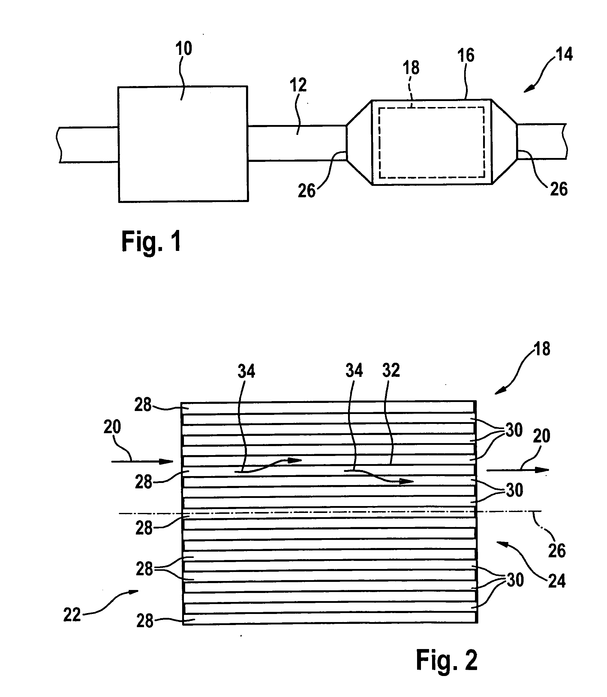
[0022]In FIG. 1, an internal combustion engine bears the reference character 10. Exhaust gases are directed through an exhaust pipe 12 to an emissions control system 14. The latter encompasses a particle filter 16 with which carbon particles are filtered out of the exhaust gas flowing in exhaust pipe 12. This is necessary especially in diesel internal combustion engines in order to comply with regulatory stipulations.

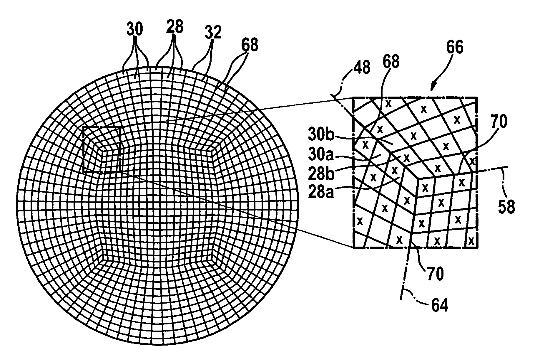
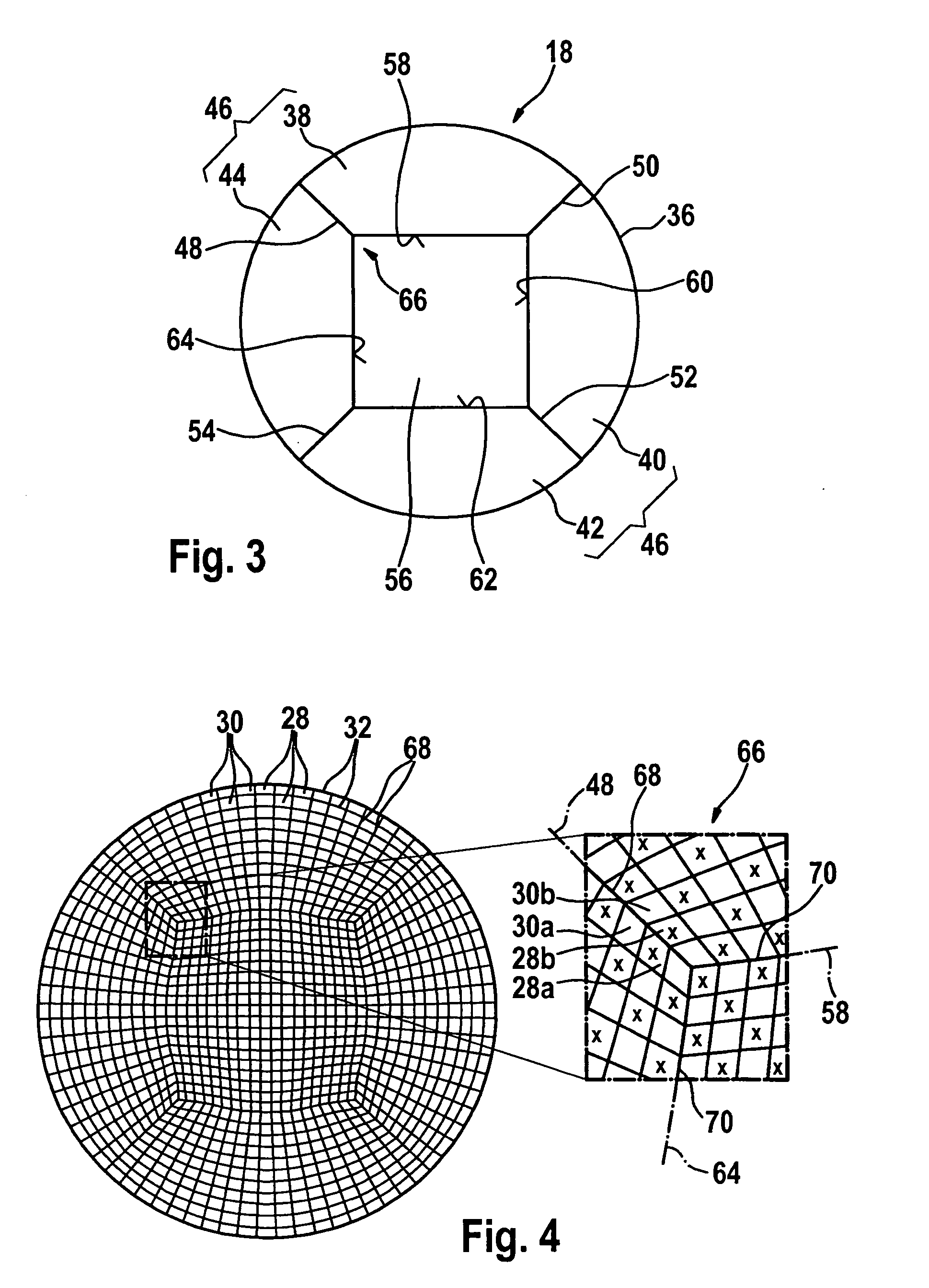
[0023]Particle filter 16 encompasses a filter element 18 that is substantially cylindrical in its entirety.

[0024]FIG. 2 depicts filter element 18 in a longitudinal section. Filter element 18 can be manufactured, for example as an extruded shaped member, from a ceramic material such as, for example, cordierite.

[0025]Exhaust gas of internal combustion engine 10 flows through filter element 18 in the direction of arrows 20. In FIG. 2 an entrance surface for the exhaust gas to be filtered carries the reference character 22, and an exit surface for filtered exhaust gas carri...


PUM

PropertyMeasurementUnit
angleaaaaaaaaaa
angleaaaaaaaaaa
angleaaaaaaaaaa

Abstract

A filter element, especially for filtering exhaust gases of an internal combustion engine, having inlet channels that are open at the input end and closed at the output end in the flowthrough direction, and having outlet channels that are closed at the input end and open at the output end in the flowthrough direction, the inlet channels and outlet channels being delimited by filter walls, the profile of at least some of the filter walls of an outer region of the filter element being adapted to the profile of an at least locally curved outer side of the filter element.

Description

FIELD OF THE INVENTION[0001]The present invention relates to a filter element, especially for filtering exhaust gases of an internal combustion engine, and to a particle filter and to an exhaust emissions control system having a filter element.BACKGROUND INFORMATION[0002]The exhaust gas to be purified flows through the open-pore filter walls disposed between the entrance channels and exit channels. With time, carbon particles become deposited on the upstream surfaces of the filter walls. These carbon particles result in a decrease in the permeability of the filter walls, and consequently in an increase in the pressure drop that occurs as the gas flow passes through the filter walls. The so-called exhaust gas counterpressure correspondingly rises. When it exceeds a specific value, the filter is regenerated by combusting the deposited carbon particles. For this, the temperature of the exhaust gas directed through the filter element can be increased. This is brought about, for example,...

Claims


Application Information

Patent Timeline
Patent Type & Authority Applications(United States)
IPC IPC(8): B01D46/24F01N13/08
CPCB01D46/2451Y02T10/20B01D46/247B01D46/2474B01D2046/2481C04B38/00C04B2111/00129C04B2111/00793F01N3/0222F01N2260/10F01N2330/06F01N2330/30B01D46/2455C04B35/195Y02T10/12B01D46/249B01D46/2482B01D46/2478B01D46/2486
Inventor DIETZHAUSEN, HJOLGERMICHAELIS, BURKHARDHILLER, PETERHOEFFKEN, TOBIAS
Owner ROBERT BOSCH GMBH
Learn More