Methods and systems for drilling auxiliary holes

a technology of auxiliary holes and methods, applied in the direction of drilling pipes, drilling with mechanical conveying, rotary drilling, etc., can solve the problems of inaccurate drilling angles, difficult to maintain a precise drilling angle, and danger to employees and personnel, and achieve the effect of saving tim

Active Publication Date: 2009-12-29
NAT OILWELL VARCO LP
View PDF25 Cites 9 Cited by
  • Summary
  • Abstract
  • Description
  • Claims
  • Application Information

AI Technical Summary

Benefits of technology

[0012]In certain aspects, the drive unit is secured to a mount structure that can be connected to the support frame within a range of angles with respect to the support frame. This makes it possible to drill the auxiliary hole at a desired angle to the drill floor. To accommodate non-flat ground on which the rig is located, the auger drive unit is raised or lowered and / or its angle with respect to the rig and ground is adjusted.
[0016]In certain aspects, with systems according to the present invention precision, accuracy, portability, efficiency are increased. With a unit according to the present invention precise holes can be drilled from the drill floor in exactly the correct spot and angle.
[0019]In certain aspects, units according to the present invention use hydraulics and winch lines from the crown, and there is, therefore, no need for the mud system to drill auxiliary holes. While some crew members drill the auxiliary holes, other crew members can set up the mud system thus saving time.

Problems solved by technology

A variety or problems are associated with the use of such rigs; often including difficulties in transporting such rigs to remote locations where the main wellbore is to be drilled.
Often, if auxiliary hole drillers are not available or cannot reach the drill site, some drillers use the kelly to drill these holes.
Using the kelly to drill these holes can be dangerous to employees and personnel, since the workers have to pull the kelly over by hand or with winches to these holes and the resistance and weight of this equipment can make it difficult to maintain a precise drilling angle.
This can lead to inaccurate angles for these holes which is undesirable.
Guiding the drilling of an auxiliary hole with a kelly can be extremely difficult.
The drill bit can move in any direction and precision can be lost.

Method used


Image

  • Methods and systems for drilling auxiliary holes
  • Methods and systems for drilling auxiliary holes
  • Methods and systems for drilling auxiliary holes

Examples


Embodiment Construction

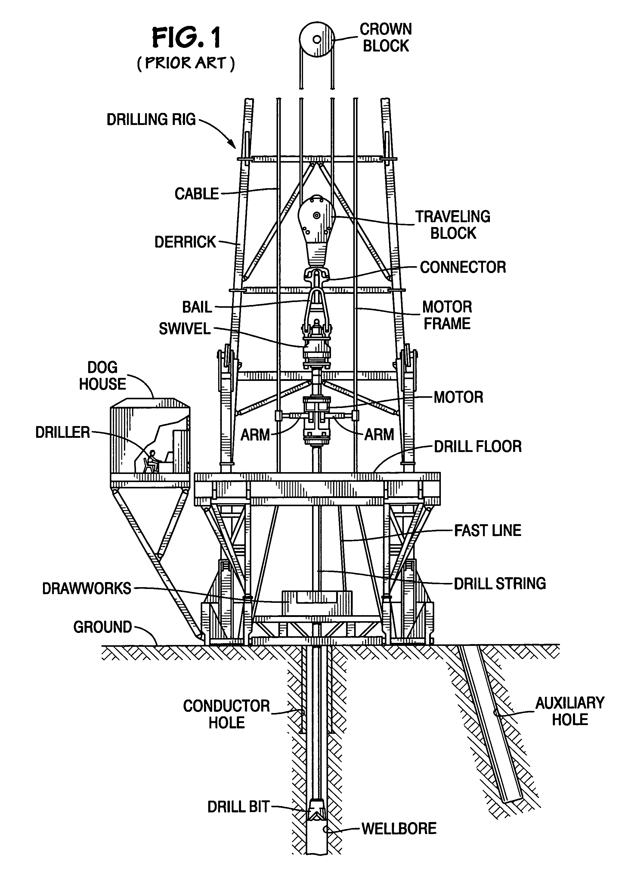
[0075]FIG. 1 illustrates a prior art drilling rig which, as shown, has a top drive system for rotating a drill string; but as is well-known, any suitable rotary apparatus on a drill floor may be used for this purpose. The prior system as shown in FIG. 1 has a drilling rig with a rig floor, a derrick, a crown block, and strands of a cable, by which a traveling block is vertically positioned. A lower end of the traveling block is connected to an upper end of a swivel. The swivel is supported by bails from a connector. A drilling motor has a hollow output shaft that directly drives a drill string with a drill bit used for drilling a main wellbore. The motor has opposed arms attached to a motor frame. The traveling block moves vertically within the derrick and the swivel, motor, and drill string are carried therewith. A drawworks drive is positioned to accept the marginal end of a cable about a drawworks drum. A dog house houses control panels and electronic circuitry for controlling th...


PUM


Abstract

Systems and methods for drilling auxiliary holes such as conductor holes, ratholes, and mouseholes useful in drilling operations. The systems and methods include the use of a portable drilling apparatus that is selectively mountable on a rig's drill floor and is removable after an auxiliary hole has been drilled. A movable drive unit is pulled down by a cable system forcing the drive unit down and thereby facilitating drilling of the auxiliary hole.

Description

BACKGROUND OF THE INVENTION[0001]1. Field of the Invention[0002]This invention is directed to wellbore drilling operations; systems for drilling auxiliary holes such as conductor holes, ratholes, and mouseholes useful in such operations; and methods of forming such auxiliary holes.[0003]2. Description of Related Art[0004]The prior art discloses a variety of methods and systems for drilling operations; for example, and not by way of limitation, those disclosed in U.S. Pat. Nos. 2,810,550; 3,340,938; 3,719,238; 3,807,109; 3,922,825; 3,942,593; 4,269,395; 4,290,495; 4,368,602; 4,421,179; 4,442,904; 4,489,526; 4,569,168; 4,809,788; 4,837,992; 4,875,530; 5,038,871; 5,199,507; 5,351,767; 5,468,121; 5,544,978; 6,209,851; 6,634,436; 6,523,319 and the references cited in these patents—all these patents incorporated fully herein for all purposes. The formation of auxiliary holes such as conductor holes, ratholes, and mouseholes and the use of such holes is common in such drilling operations. ...

Claims


Application Information

Patent Timeline
Patent Type & Authority Patents(United States)
IPC IPC(8): E21B7/00B23Q5/00E21B19/14
CPCE21B3/02E21B7/026E21B7/005E21B3/022
Inventor STOIK, RANDY STEVEN
Owner NAT OILWELL VARCO LP
Why Eureka
Try Eureka