Method and device for generating retinal images using the stigmatism of the two foci of a substantially elliptical sight

Inactive Publication Date: 2009-12-29
LASTER SA
View PDF6 Cites 34 Cited by
  • Summary
  • Abstract
  • Description
  • Claims
  • Application Information

AI Technical Summary

Benefits of technology

[0021]By using a substantially elliptical diopter, it is further possible to reduce the diameter of the whole of the light beams forming the image in the vicinity of the so-called “source” focus where the sourc

Problems solved by technology

Thus, these devices similar to overhead projectors

Method used


Image

  • Method and device for generating retinal images using the stigmatism of the two foci of a substantially elliptical sight
  • Method and device for generating retinal images using the stigmatism of the two foci of a substantially elliptical sight
  • Method and device for generating retinal images using the stigmatism of the two foci of a substantially elliptical sight

Examples


Embodiment Construction

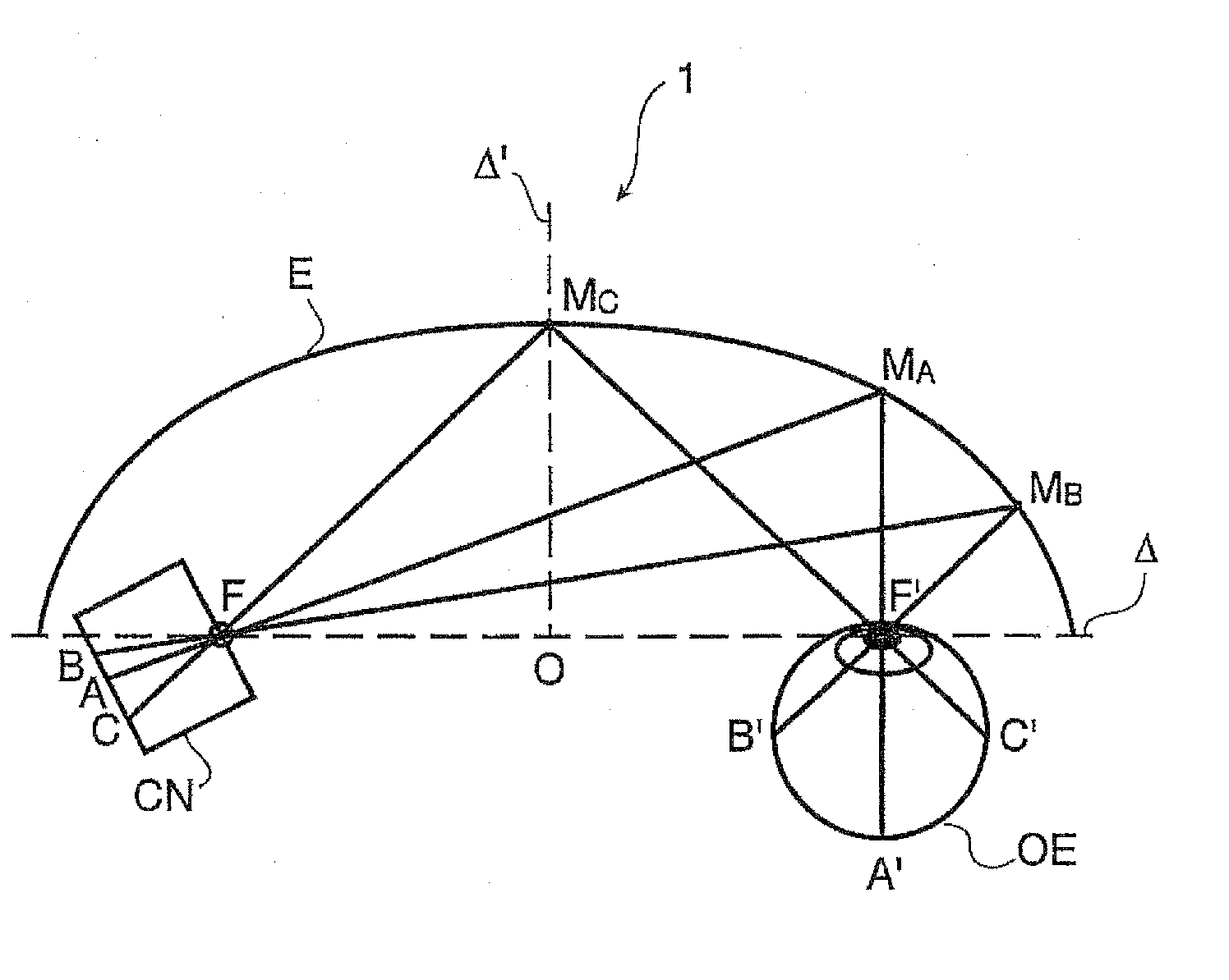
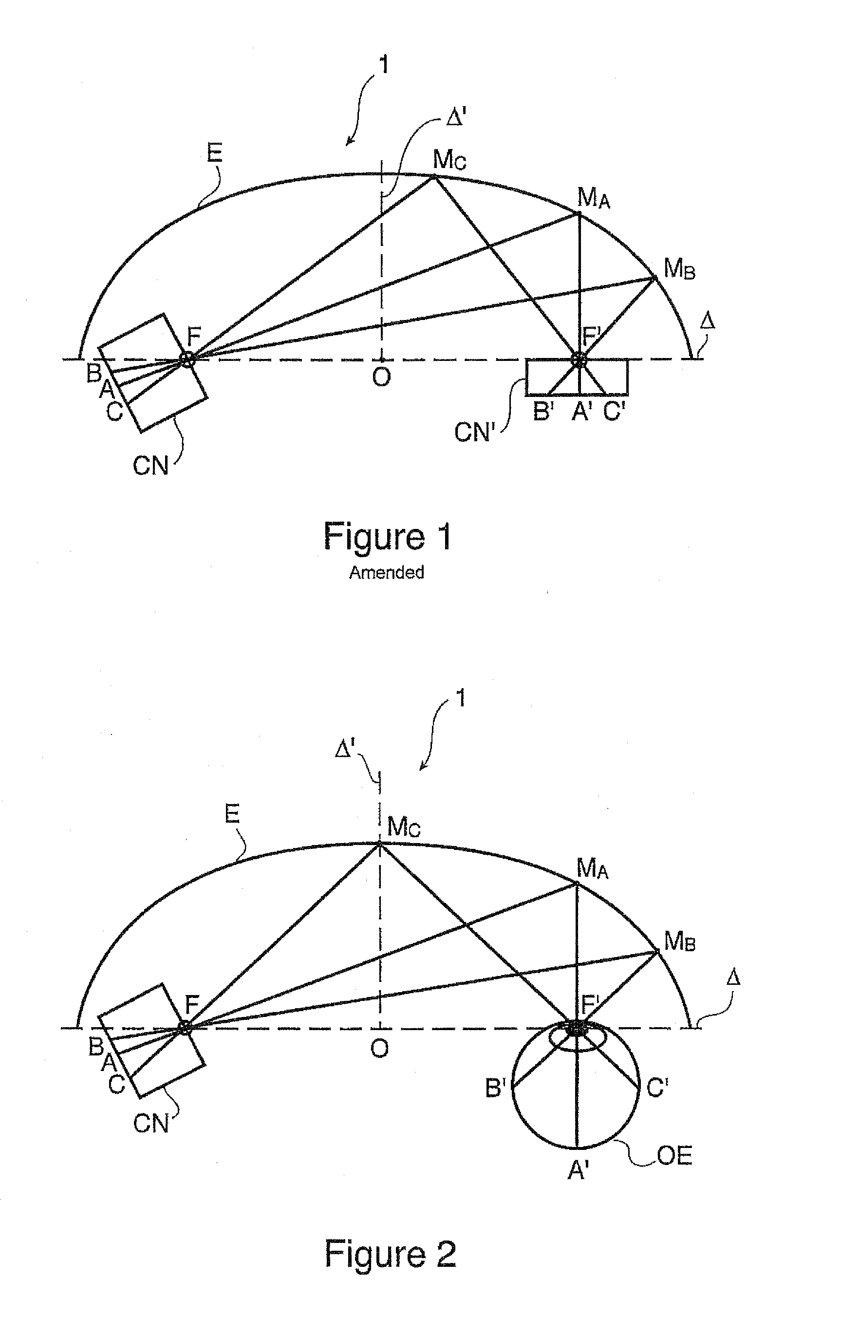
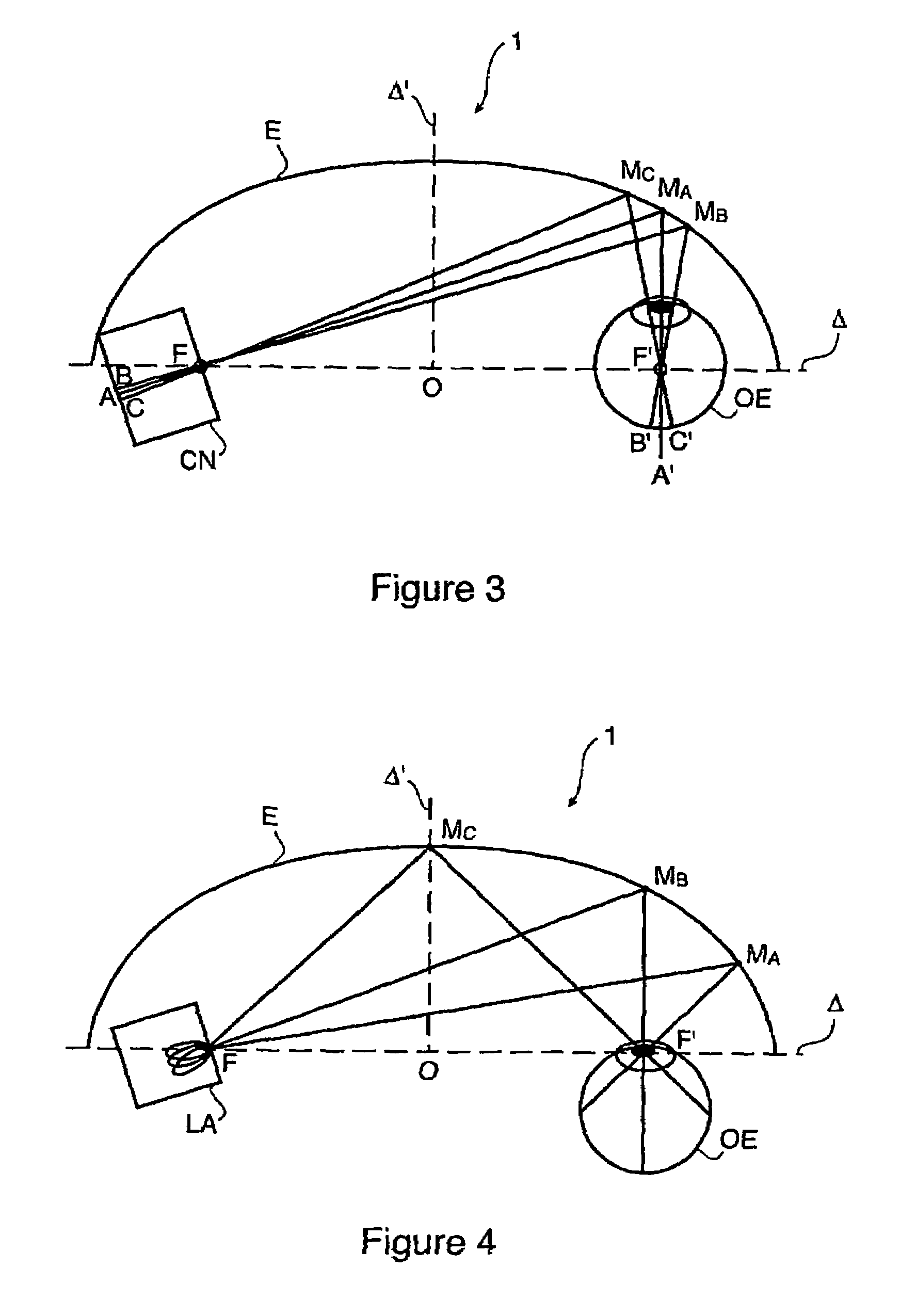
[0044]In the example illustrated in FIG. 1, the device 1 according to the invention consists of:[0045]a substantially elliptical diopter illustrated by the half-ellipse E defined by its major axis Δ, its minor axis Δ′, its centre O and its two foci F, F′ located on the major axis Δ, on either side of the centre O,[0046]two dark rooms CN, CN′, the pupils of which are respectively located in the vicinity of the foci F, F′.

[0047]Thus, the beams from the dark room CN, pass through the pupil of said dark room CN, and are then reflected on the concave wall of the optical diopter to reach the dark room CN′ after having passed through the pupil of said dark room CN′; three rays symbolize the trajectory of the aforesaid beams, i.e.:[0048]ray AMAA′ from the source point A of the dark room CN, reflected in the vicinity of the point MA on the ellipse and then ending up at the image point A′ of the dark room CN′,[0049]ray BMBB′ from the source point B of the dark room CN, reflected in the vicini...


PUM


Abstract

A method for generating retinal images using the stigmatism of the two foci (F, F′) of a substantially elliptical sight (E) with a semi-reflective surface, wherein a so-called object focus consisting of the diaphragm of a pinhole disc forming the convergence point of an image generated by a light-emitting display or a collimated light source is positioned adjacent to the first focus (F) of the substantially elliptical sight (E), a so-called image focus consisting of the pupil or the centre of the user's eye (OE) is positioned adjacent to the second focus (F′) of said substantially elliptical sight (E), and the image generated by said light-emitting display or said collimated light source and reflected by the semi-reflective surface of the substantially elliptical sight (E) is projected adjacent to the retina of the user's eye.

Description

BACKGROUND OF THE INVENTION[0001]1. Field of the Invention[0002]The present invention relates to a method for generating retinal images using the stigmatism of two foci of a substantially elliptical diopter.[0003]More particularly, its object is to solve problems of viewing virtual realities or augmented realities, by the retina of the eye.[0004]Generally, it is known that many studies have been carried out in the field of displaying of information superimposed on the vision of the environment captured by the retina of the eye.[0005]2. Description of Prior Art[0006]These methods intended for military applications during first developments in the 1960s, consist of projecting on a semi-reflecting transparent surface, symbols and information relating to the piloting of the aircraft, i.e., in this case, a horizon line, speed, altitude and guiding information for approaching the landing runway. These devices, so-called high head collimators, facilitate the piloting of the aircraft by all...

Claims


Application Information

Patent Timeline
IPC IPC(8): A61B3/10G02B27/14G02B5/10G02B17/06G02B26/10G02B27/00G02B27/01
CPCG02B17/06G02B27/0172G02B5/10G02B2027/0123G02B2027/011G02B27/01G02B17/00
Inventor LIU, ZILEHAMDANI, RACHID
Owner LASTER SA
Why Eureka
Try Eureka