Bi-directional DC-DC converter

a dc-dc converter and bi-directional technology, applied in the direction of dc-dc conversion, power conversion systems, instruments, etc., can solve the problem of no way to minimize, and achieve the effect of reducing the recovery loss of a diod

Active Publication Date: 2009-12-29
NAGOYA UNIVERSITY +1
View PDF2 Cites 6 Cited by
  • Summary
  • Abstract
  • Description
  • Claims
  • Application Information

AI Technical Summary

Benefits of technology

[0017]The recovery-less step-up chopper circuit as illustrated in FIG. 1 reduces a recovery loss of a diode during a step-up operation.
[0018]On the other hand, the vehicle employing the recovery-less step-up chopper circuit of FIG. 1 also employs, for example, a step-down chopper circuit that conducts a regenerative operation, and in the regenerative operation, there is no way to minimize a loss caused by the recovery of a diode arranged in the step-down chopper circuit.
[0019]The present invention provides a bi-directional DC-DC converter capable of eliminating a diode recovery loss during a regenerative operation, as well as a diode recovery loss that occurs during a normal operation, thereby improving the efficiency of the converter.

Problems solved by technology

On the other hand, the vehicle employing the recovery-less step-up chopper circuit of FIG. 1 also employs, for example, a step-down chopper circuit that conducts a regenerative operation, and in the regenerative operation, there is no way to minimize a loss caused by the recovery of a diode arranged in the step-down chopper circuit.

Method used


Image

  • Bi-directional DC-DC converter
  • Bi-directional DC-DC converter
  • Bi-directional DC-DC converter

Examples


embodiment 1

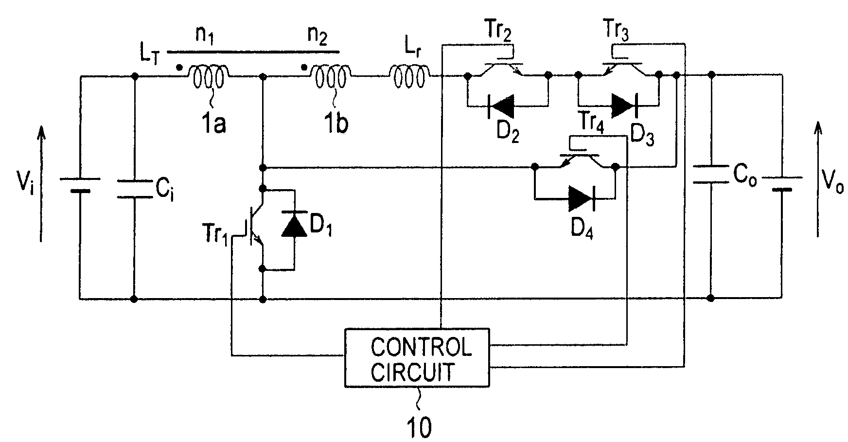
[0038]FIG. 4 is a circuit diagram illustrating a bi-directional DC-DC converter according to Embodiment 1 of the present invention. The bi-directional DC-DC converter illustrated in FIG. 4 steps up a DC voltage of a first DC power source Vi and supplies power to a second DC power source Vo. Also, the bi-directional DC-DC converter of FIG. 4 steps down a DC voltage of the second DC power source Vo and supplies power to the first DC power source Vi. Namely, the bi-directional DC-DC converter of Embodiment 1 is a step-up chopper circuit provided with a regenerative function so that it operates as a step-down chopper circuit in a regenerative mode.

[0039]In FIG. 4, ends of the first DC power source Vi are connected to a smoothing capacitor Ci and ends of the second DC power source Vo are connected to a smoothing capacitor Co.

[0040]A first reactor LT has a first winding 1a of n1 as the number of turns and a second winding 1b of n2 as the number of turns. The first and second windings 1a a...


PUM


Abstract

A bi-directional DC-DC converter includes a first series circuit connected to ends of a first DC power source and including a first winding of a first reactor and a first switch; a second series circuit connected to ends of the first switch and including a second winding of the first reactor, a second reactor, a second switch, a third switch, and a second DC power source; a third series circuit connected to the ends of the first switch and including a fourth switch and the second DC power source; and a control circuit configured to turn on / off the switches and thereby carry out step-up and step-down operations between the first and second DC power sources.

Description

BACKGROUND OF THE INVENTION[0001]1. Field of the Invention[0002]The present invention relates to a bi-directional DC-DC converter for carrying out a step-up operation and a step-down operation.[0003]2. Description of the Related Art[0004]A recovery-less step-up chopper circuit is known to serve as a high-efficiency, low-noise power converter for a vehicle. FIG. 1 is a circuit diagram illustrating a recovery-less step-up chopper circuit according to a related art. In FIG. 1, an AC power source Vac is connected to a full-wave rectifying circuit B1. The circuit B1 rectifies an AC power source voltage from the AC power source Vac and outputs the rectified voltage to a positive output end P1 and a negative output end P2.[0005]Between the positive and negative output ends P1 and P2 of the full-wave rectifying circuit B1, there is connected a first series circuit that includes a step-up winding 5a (whose number of turns being n1) of a step-up reactor L1, a winding 5b (whose number of turns...

Claims


Application Information

Patent Timeline
Patent Type & Authority Patents(United States)
IPC IPC(8): H02J1/00
CPCH02M3/1584H02M3/1582
Inventor ASUKE, HIDEKITAKANO, HIDEHARUKANAZAWA, MASAKITSURUYA, MAMORUYAMAMOTO, MASAYOSHIHARA, HIROTAKAFUNABIKI, SHIGEYUKI
Owner NAGOYA UNIVERSITY
Why Eureka
Try Eureka