Slave circuit for distributed power converters in a solar module

a solar module and slave circuit technology, applied in the field of integrated circuits, to achieve the effect of less cos

Active Publication Date: 2016-05-31
SUNEDISON MICROINVERTER PROD
View PDF23 Cites 0 Cited by
  • Summary
  • Abstract
  • Description
  • Claims
  • Application Information

AI Technical Summary

Benefits of technology

[0007]In an alternative specific embodiment, the present invention provides a method of operating an inverter device for a solar module. The method includes receiving an input voltage at a DC input from a solar cell group, and receiving the DC input and increasing the input voltage from the input to an intermediary voltage using a preliminary boost circuit. The method also includes receiving the DC input at the intermediary voltage at a DC boost circuit, coupled to the preliminary boost circuit, and outputting a DC output having an AC RMS peak voltage and receiving the DC output having the AC RMS peak voltage at a rectifier circuit, coupled to the DC boost circuit. The method includes wave shaping the DC output to a half wave rectified DC waveform at a rectifier output. The method also includes receiving the half wave rectified DC waveform at an energy recovery circuit and storing a reverse recovery charge at a storage device configured with the energy recovery circuit. The method includes transferring the reverse recovery charge from the storage device to an output of a DC bus structure to reduce a diode recovery loss in the rectifier circuit.
[0011]Many benefits are achieved by ways of present invention. For example, the present invention uses an integrated solar inverter device, having a master-slave architecture, on a back plane coupled to a solar module. The present solar module is efficient and less costly than conventional solar modules with external inverters connected through a junction box. Additionally, the inverter device comprises a slave circuit and master circuit. Depending on the embodiment, one or more of the benefits can be achieved. These and other benefits will be described in more detailed throughout the present specification and particularly below.

Problems solved by technology

In addition the lower system efficiencies (Solar-panel to grid / end point of load), hovering around 80%, have been an area of concern as they contribute to significant capital expenditure and O&M costs.

Method used


Image

  • Slave circuit for distributed power converters in a solar module
  • Slave circuit for distributed power converters in a solar module
  • Slave circuit for distributed power converters in a solar module

Examples


Embodiment Construction

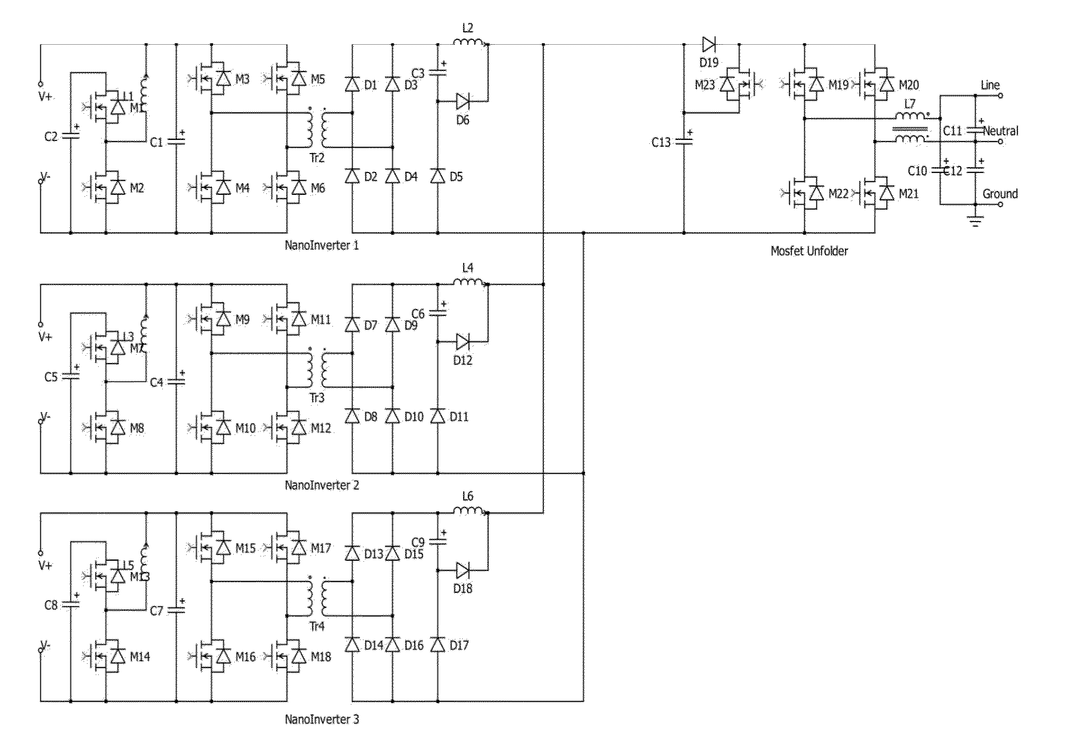
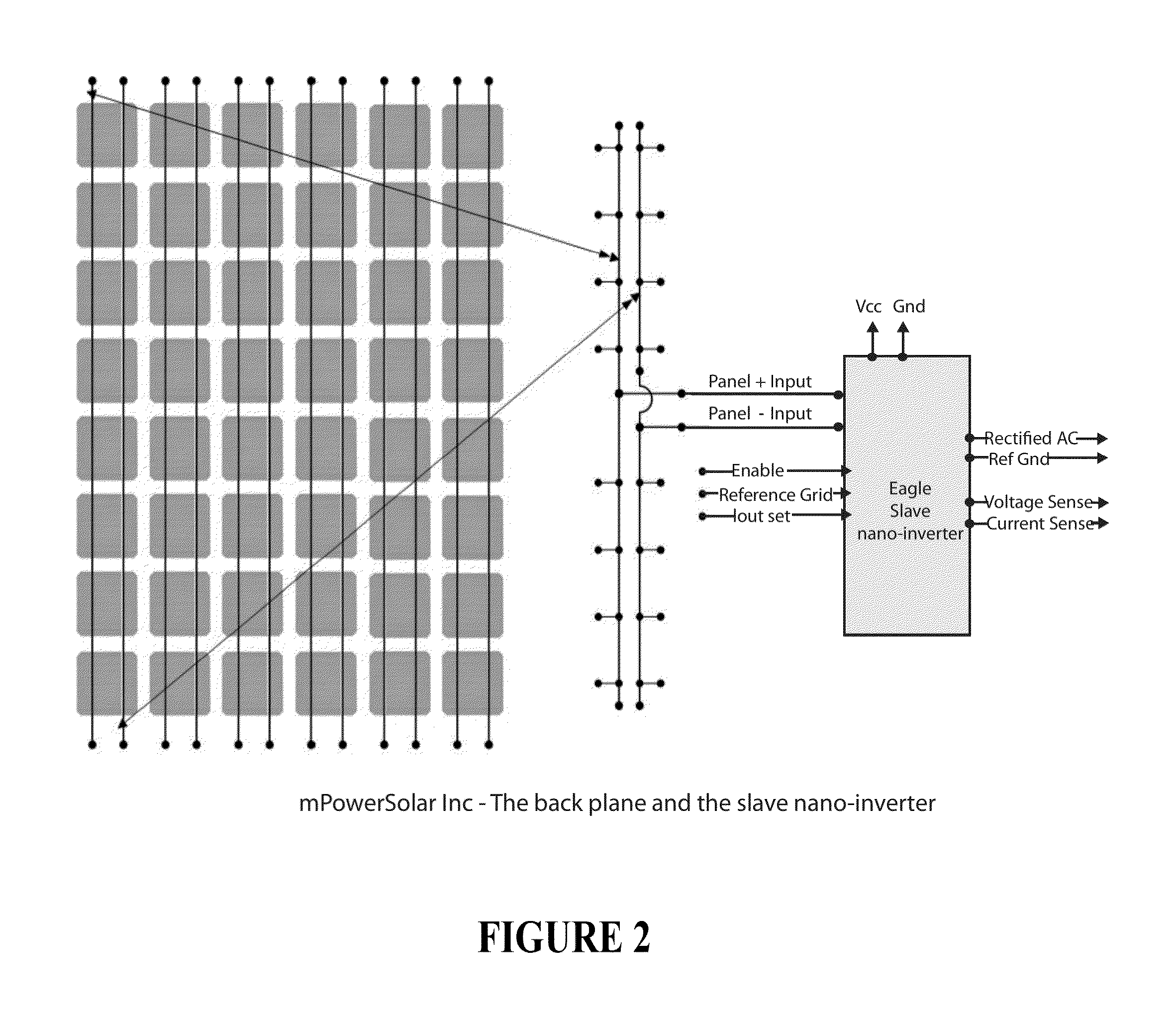
[0027]The present disclosure generally relates to integrated circuits. More particularly, the present disclosure provides a method and system for an inverter device including a slave circuit architecture configured for a solar module. Merely by way of example, the inverter device can be coupled to a backplane of a solar module, including a plurality of solar cells. Of course, there can be other variations, modifications, and alternatives.

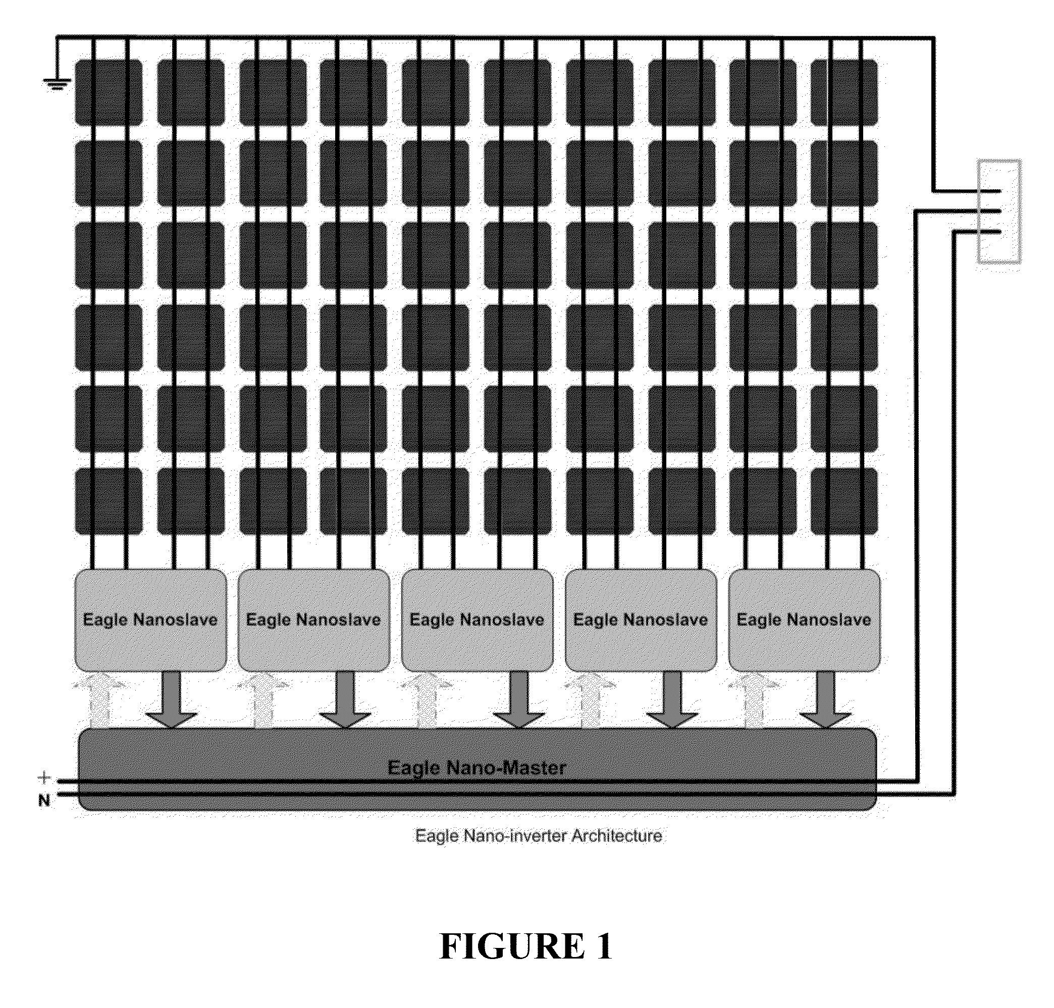
[0028]As PV panel increase in rated output power, the notion of running at the Maximum Power Point (MPP) has been a preliminary requirement to maximize the power generation. In addition “stringing” PV panels, which can differ in their MPP points by + / −3-5% usually results in almost all panels being run at sub-optimal power points. Further the effects of shading and soiling, which contribute to higher loss, get amplified in string topologies. As a result, central inversion and string inversion topologies have substantially lower system efficiencies. ...


PUM


Abstract

An inverter device for a solar module. The inverter device comprises a slave circuit device that includes an input comprising a DC input from a solar cell group and a preliminary boost circuit. A DC boost circuit is coupled to the preliminary boost circuit and configured to boost the intermediary voltage to an AC RMS peak voltage. A rectifier circuit is coupled to the DC boost circuit. An energy recovery circuit comprises a storage device coupled to the rectifier output. The energy recovery circuit is configured to temporarily store a reverse recovery charge and transfers the reverse recovery charge to an output of a DC bus structure to reduce a diode recovery loss in the rectifier circuit.

Description

CROSS-REFERENCE TO RELATED APPLICATIONS[0001]The present invention claims priority to and is a continuation-in-part of U.S. application Ser. No. 13 / 660,752 filed Oct. 25, 2012. That application is herein by incorporated by reference for all purposes.BACKGROUND OF THE DISCLOSURE[0002]The present disclosure generally relates to integrated circuits. More particularly, the present disclosure provides a method and system for inverter device including a slave circuit architecture configured for a solar module. Merely by way of example, the inverter device can be coupled to a backplane of a solar module, including a plurality of solar cells. Of course, there can be other variations, modifications, and alternatives.[0003]Since the discovery of the photoelectric effect, solar inverters have been designed to convert direct current (DC) electricity produced by solar cells or panels into alternating current (AC). The circuits termed inverters originally refer to the process of constantly invert...

Claims


Application Information

Patent Timeline
Patent Type & Authority Patents(United States)
IPC IPC(8): H02J1/12H02M7/5387H02M1/34H02J3/38H02M1/00
CPCH02M7/5387H02J3/383H02M1/34H02M2001/007H02M2001/0051H02M2001/346Y02B70/1491Y02E10/563H02J2300/24H02J3/381Y02B70/10Y02E10/56H02M1/0051H02M1/346H02M1/007H02J2300/26H02J3/388H02J3/46
Inventor POTHARAJU, SURYANARAYANAJAYARAMAN, VIJAY SHANKAR
Owner SUNEDISON MICROINVERTER PROD
Why Eureka
Try Eureka