Point source localization sonar system and method

a sonar system and point source technology, applied in the field of sonar systems and methods, can solve the problems of reducing accuracy, requiring manual interaction, and extremely time-consuming processes, and achieve the effect of low cost and minimal space requirements

Inactive Publication Date: 2009-12-29
UNITED STATES OF AMERICA
View PDF4 Cites 1 Cited by
  • Summary
  • Abstract
  • Description
  • Claims
  • Application Information

AI Technical Summary

Benefits of technology

[0020]It is still another object of the present invention is to provide a point source localization sonar system and method of use that uses high resolution bearing, range, and depth estimates of the contact and own-ship position to estimate contact position, course, and speed in real-time providing a continuous target motion analysis capability.
[0021]Yet another object of the present invention is to provide a point source localization sonar system and method of use that provides a user interface permitting the user to steer the search region (in bearing range, depth, and frequency) and on / off switches giving the user control over display processing of the entire system.
[0024]Another object is to provide a point source localization sonar system and method of use that has minimal space requirements making it suitable for shipboard deployment on both surface ships and submarines.
[0025]It is yet another object to provide a point source localization sonar system and method of use that is of comparatively low cost.
[0027]In accordance with the foregoing objects, the preferred embodiment of the present invention comprises a matched-field based sonar system and method of use that supports real-time, passive, three-dimensional acoustic source localization using a mobile, horizontal array. The system continuously receives and processes acoustic array, non-acoustic array, and own-ship navigational data in the matched-field process (MFP). Driven by own-ship and array status, a global bathymetry database and an acoustic environmental model are used to generate replicas for the MFP. If a three-dimensional tracker is assigned, then the tracker will automatically steer the search region to maintain contact on the target of interest. A variety of displays are provided to the user including tracker displays (which provide tracker information), MFP ambiguity surface displays (which support contact localization), and non-acoustic and navigational displays (which show status of own-ship and array). A user control interface allows a user to control the search region in bearing, range, depth, and frequency; assign the three-dimensional tracker function; and control display processing.

Problems solved by technology

This process is extremely time-consuming and requires manual interaction.
Sonar processors that disregard the effect of array cant will erroneously report contacts at an erroneous bearing.
For a single line towed array, it provides only bearing information however, and accuracy diminishes as the acoustic source moves from broadside to end-fire.
However, these range estimates have very coarse resolution and like plane wave beamforming, this technique has performance degradation at end-fire.
Both plane wave and range focused beamforming cannot resolve the port / starboard ambiguity issues when using a linear array and neither provide depth estimates.
This process is tedious, prone to error, and requires the operator to know the acoustic environment.
All of the acoustic-source localization techniques described thus far also do not work well in shallow water.
This technique is very computational and expensive, and to date this has prohibited use in real-time applications.
Systems incorporating matched-field processing thus far have been restricted to the laboratory where very small data sets are processed over very restricted search regions (bearing, range, depth, and frequency).
Although the above-described acoustic source localization methods as well as others have furthered technological development, none of the methods provide a low-cost system which incorporates a computationally efficient matched-field processing algorithm supporting real-time processing, a global bathymetry database allowing the system to operate in any oceanographic location, and other features including dynamic array shape compensation and high resolution range and bearing estimates.

Method used


Image

  • Point source localization sonar system and method
  • Point source localization sonar system and method
  • Point source localization sonar system and method

Examples


Embodiment Construction

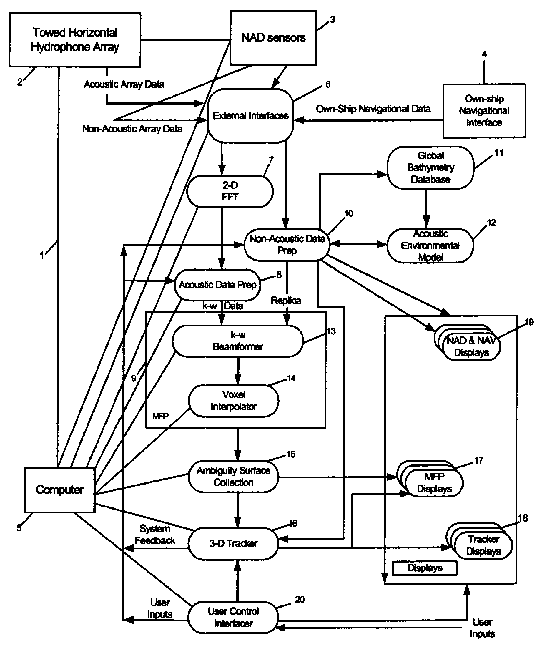
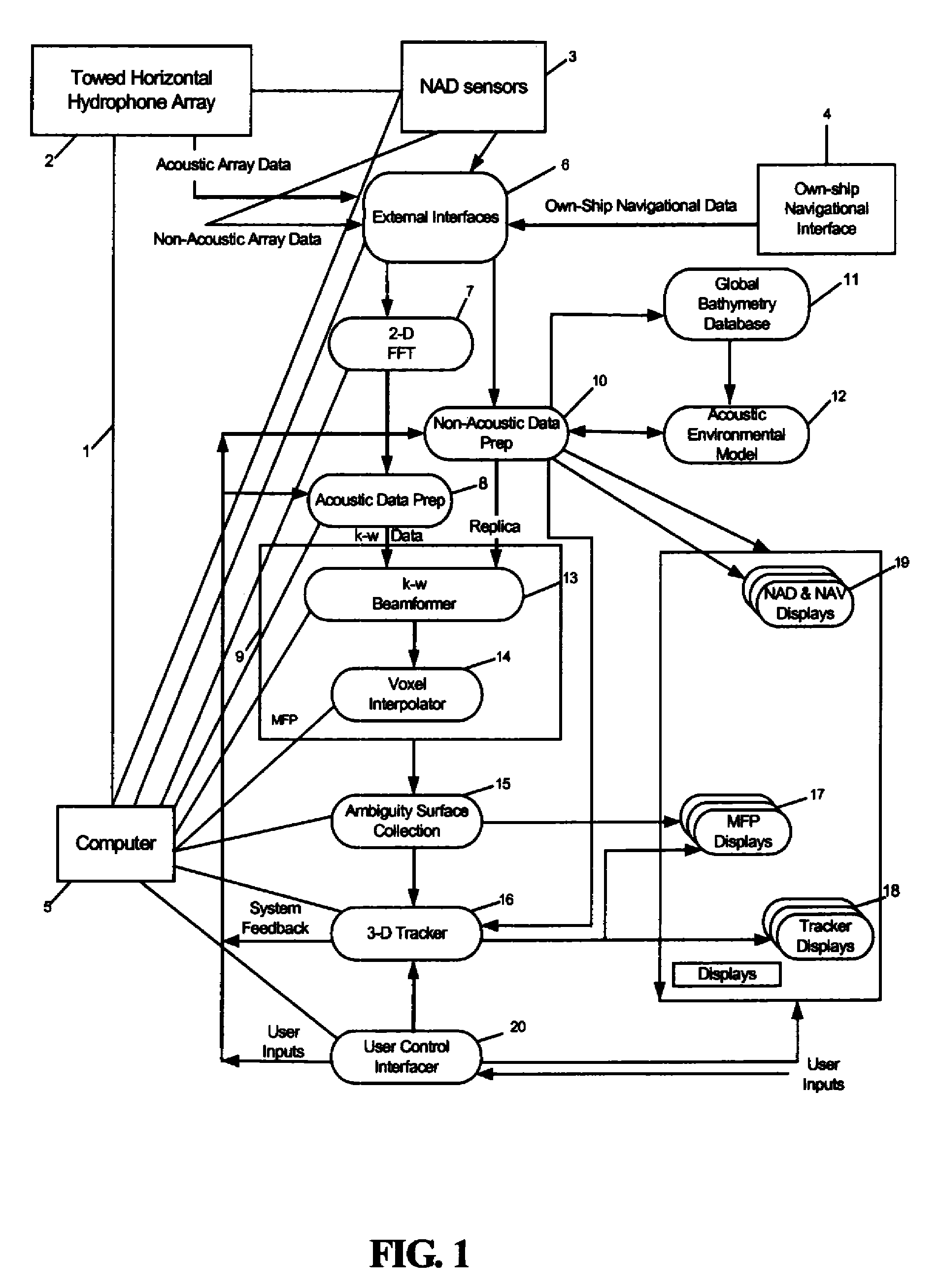
[0037]The present invention is a matched-field based point source localization (PSL) sonar system 1 and method of use.

[0038]FIG. 1 is a block diagram of the point source localization (PSL) sonar system 1. The PSL system 1 includes a towed, mobile, single-line horizontal hydrophone array 2 along with non-acoustic data (NAD) sensors 3, and an own-ship navigational interface 4. The array 2 receives acoustic signals in the water by hydrophones. The array 2 is also equipped with non-acoustic sensors 3 to allow measurement of forward and aft depth, heading, and temperature status. Certain horizontal mobile arrays 2 can be modified to provide data from two different sets of non-acoustic sensors 3, one being from standard non-acoustic array data (NAD) sensors and the other from optional Engineering Modules (EMODs) which provide greater accuracy.

[0039]For purposes of the present invention one or both sets of non-acoustic sensors 3 may be utilized, though both are preferred. The data is colle...


PUM


Abstract

A matched-field based sonar system and method of use that supports real-time, three-dimensional acoustic source localization using a mobile, horizontal array. The system receives and processes acoustic array, non-acoustic array, and own-ship navigational data in the matched-field process (MFP). Driven by own-ship and array status, a global bathymetry database and an acoustic environmental model are used to generate replicas for the MFP. If a three-dimensional tracker is assigned, then the tracker will steer the search region to maintain contact on the target of interest. Displays are provided to the user including tracker displays (which provide tracker information), MFP ambiguity surface displays (which support contact localization), and non-acoustic and navigational displays. A control interface allows a user to control the search region in bearing, range, depth, and frequency; assign the three-dimensional tracker function; and control display processing.

Description

STATEMENT OF GOVERNMENT INTEREST[0001]The invention described herein may be manufactured and used by or for the Government of the United States of America for governmental purposes without the payment of any royalties thereon or therefore.CROSS-REFERENCE TO RELATED APPLICATIONS[0002]The present invention relates to U.S. patent application Ser. No. 11 / 699,246; filed 30 Jan. 2007 and entitled “Method For Real-Time Matched Field Processing” by the inventor, W. Robert Bernecky.BACKGROUND OF THE INVENTION[0003](1) Field of the Invention[0004]The present invention generally relates to sonar systems and methods and, more specifically, to a matched-field based sonar system and method that supports real-time, passive, three-dimensional acoustic-source localization using a mobile horizontal array.[0005](2) Description of Prior Art[0006]Sonar systems detect and locate underwater objects, including missiles, torpedoes, and submarines. Active sonar systems transmit and receive in a set direction...

Claims


Application Information

Patent Timeline
Patent Type & Authority Patents(United States)
IPC IPC(8): H04B11/00
CPCG01S3/8083
Inventor BERNECKY, W. ROBERTKRZYCH, MATTHEW J.
Owner UNITED STATES OF AMERICA
Why Eureka
Try Eureka